
Installation Owner's manual

Rockwell Automation Publication CHPS-UM001D-EN-P - July 2014 93
Start-up Guide for CHPS-Series Stage with Ultra3000 Drive and Ultraware Software Appendix D
• All Ultra drive electrical parameters are defined phase-to-phase. Standard
CHPS-Series stage motors are specified phase-to-phase. If necessary, use
the following conversion.
phase-to-phase = 2 x phase-to-neutral
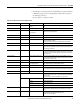
Table 14 - Linear Motor Parameter File (.mdb extension)
Parameter Units Enter Comment
Force Constant N/A
0-peak
Motor’s linear region force
constant
Convert if necessary. Standard CHPS-Series stage motors specify the correct unit
value.
Mass kg Motor model coil mass Standard CHPS-Series stages are intended for moving coil (slide) use.
Electrical Cycle Length m 0.05 for LC motors
or
0.06 for LZ motors
Standard CHPS-Series stage motors specify the electrical cycle length in mm.
Electrical cycle equals 2 x magnet pitch.
Resistance Ohms Motor’s cold resistance Phase-to-phase directly from motor specifications.
Inductance mH Motor’s inductance Phase-to-phase directly from motor specifications.
Rated Voltage V AC Drive’s input AC voltage. LC motors are rated up to 460V AC.
LZ motors are rated up to 230V AC.
For stages with 0.1 um encoder option, the maximum drive input is 115V AC.
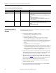
Flux Saturation table — — Leave default values.
Maximum Speed m/s Lowest maximum velocity Choose the lowest maximum velocity between the encoder or the application
restriction. The encoder maximum velocity for the Ultra3000 drive is found in the
CHPS-Series stage specifications.
Intermittent Current: A
0-peak
Motor’s peak current rating Use the motor rating in the CHPS-Series Stage Selection Guide. Do not use the
values from the Motor Product Profile. The CHPS-Series LZ motors are restricted to
3x continuous current. Consult with an application engineer if you are considering
increasing this value.
Continuous Current A
0-peak
Motor’s continuous current rating Use the motor rating in the CHPS-Series Stage Selection Guide. Do not use the
values from the Motor Product Profile. For CHPS-Series stages with cover and seals
option, derate the base value by 10%.
Max Current Boost — 0% For standard CHPS-Series stages without forced cooling.
Encoder Type — Select applicable type per CHPS-
Series stage option code
Use Incremental for digital encoder or Sine/Cosine for analog encoder. Sine/Cosine
requires additional set up per the Ultra3000 Drive manual.
Commutation Type — Sinusoidal
Startup Type — Desired commutation mode The recommended and default setting Hall Inputs and has no motion on startup.
For self-sensing, refer to the section on Self-Sensing Commutation and Startup.
Hall Input Offset degrees 0 For standard CHPS-Series stage motor models.
Lines/Meter — Enter the encoder lines per meter of travel. Lines are pre-quadrature resolution.
Alternatively, for incremental encoders, calculate the counts/meter and divide by
4 to get lines/meter.
Following are the values for the standard CHPS-Series stage encoders:
lines/m 250,000 1 μm/count incremental
500,000 0.5 μm/count incremental
2,500,000 0.1 μm/count incremental
12,500 Analog sin/cos, 20 μm period
Integral Limits — Unchecked For the standard CHPS-Series stage limits option. The standard limits option is not
compatible with the CN2 input circuit that expects an NPN open collector limit
signal.
Integral Thermostat — Check For the standard CHPS-Series stage motor options. The PTC thermistor signal is
compatible with the Ultra3000 drive thermal input circuit.
Except for very earliest Ultra Drives.