
Installation Owner's manual

92 Rockwell Automation Publication CHPS-UM001D-EN-P - July 2014
Appendix D Start-up Guide for CHPS-Series Stage with Ultra3000 Drive and Ultraware Software
Linear Motor File Parameters
The following guide supplements the information found in the Ultra3000 drive
manuals. Some of the motor parameters are critical for commutation and motor
protection. Incorrect entry of theses motor parameters can cause motor problems,
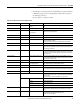
Ultraware assumes a linear motor is functionally equivalent to a rotary motor.
However, the functional equivalent to a rotary motor is a complete linear motor
driven stage. To account for the difference, the parameters highlighted in bold in
the Linear Motor Parameter File (.mdb extension)
table shown below must be
adjusted to stage level specifications.
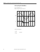
Creating a CHPS-Series Stage
Motor File
Complete CHPS-Series stage motor specifications are in the linear motor
specifications information contained in this manual or the motor’s data sheet.
Identify the stage motor option for your CHPS-Series stage and use the
corresponding data.
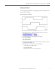
Conversion Factors:
• Ultra3000 drive ampere units are measured at the peak of the sine wave,
not RMS. Standard CHPS-Series stage motors are rated both ways. Be sure
to select the correct value. If necessary, use the following conversion.
ampere peak = 1.4 x RMS
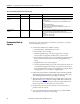
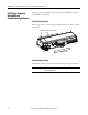
Connector Data Summary
CHPS-Series Stage Signal Designation Ultra3000 Drive
Terminal or Pin Signal Designation
Motor phase U U Motor phase U
Motor phase V V Motor phase V
Motor phase W W Motor phase W
Encoder A+ (digital) or Sin+ (analog) CN2-1 Encoder A+ (digital) or Sin+ (analog)
Encoder A - (digital) or Sin - (analog) CN2-2 Encoder A - (digital) or Sin - (analog)
Encoder B+ (digital) or Cos+ (analog) CN2-3 Encoder B+ (digital) or Cos+ (analog)
Encoder B - (digital) or Cos - (analog) CN2-4 Encoder B - (digital) or Cos - (analog)
Hall S1 CN2-12 Hall S1
Hall S2 CN2-13 Hall S2
Hall S3 CN2-8 Hall S3