
Installation Owner's manual


86 Rockwell Automation Publication CHPS-UM001D-EN-P - July 2014
Appendix B Accessories
86 Rockwell Automation Publication CHPS-UM001D-EN-P - July 2014
Appendix B Accessories
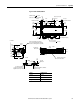
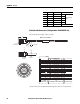
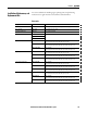
Feedback Cable Dimensions (catalog number 2090-XXNFMF-Sxx)
The maximum cable length of 10 m (32.8 ft).
1 Bend radius (BR) is the specified minimum bend radius for cable assemblies. For standard cable, BR is a one-time flex
application. Flex cables have a much higher BR to withstand flex applications. BR can vary on user-fabricated cables.
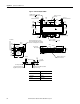
F18White BR+
Not used for CHPS
Stages
G18Black BR-
E18White 1
H18Red 2
L N/A N/A N/A
SHIELD
Pin Gauge Color Signal Designation
54
(2.1)
57
(2.2)
99
(3.9)
10
(0.4)
26
(1.0)
Dimensions are in mm (in.)
Start of
Bend Radius
Connector
Diameter
Cable
Diameter
Bend Radius
1
1
2
3
4
5
6
9
10
11
13
14
15
16
17
7
8
12
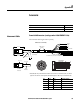
A+
A -
B+
B -
I+
I -
+5V
COM
+9V
TS+
TS -
S1
S2
S3
MTR RRAME
ABS
COM
28 AWG BLACK
28 AWG WHITE/BLACK
28 AWG RED
28 AWG WHITE/RED
28 AWG GREEN
28 AWG WHITE/GREEN
16 AWG GRAY
16 AWG WHITE/GRAY
22 AWG ORANGE
22 AWG WHITE/ORANGE
28 AWG BLUE
28 AWG WHITE /BLUE
28 AWG YELLOW
28 AWG WHITE/YELLOW
28 AWG BROWN
28 AWG WHITE/BROWN
DRAIN
1
2
3
4
5
6
7
9
8
11
16
12
13
14
17
15
10