
Installation Owner's manual

Rockwell Automation Publication CHPS-UM001D-EN-P - July 2014 79
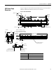
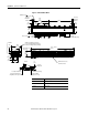
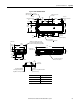
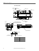
Specifications and Dimensions Appendix A
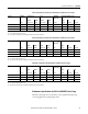
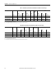
Figure 23 - CHPS-x8xxxA/D-xLMxxx
25.4
(1.0)
Slide
239
(9.41)
130.8
(5.15)
44
(1.72)
216.7
(8.53)
56
(2.20)
Ø 5.8 (0.23) Thru
Ø 9.7 (0.38) T
hru 14.2 (0.56)
120
(4.72)
30.0
(1.38)
105.5
(4.15)
55.4
(2.18)
(4X) M8 x 1.25-6H
(4X) Ø 6.8 (0.27)
12.0 (0.47)
45.2 (1.78) T
hru
215.7
(8.49)
166.6
(6.56)
28.0
(1.10)
232
(9.13)
288.9
(11.38)
46.8
(1.84)
8.5
(0.33)
37.8
(1.49)
130.8
(5.15)
200
(7.9)
5.2
(0.206)
25.4
(1.0)
25.4 (1.0)
Mechanical Overtravel
340
(13.4)
+ Travel
Bracket located ±51 (2.0)
from center of travel.
(4X) M10 x 1.5-6H Thru (2 per end cap)
Access point for lubricating linear bearings.
Provision to use lifting hooks (not provided).
Ground Screw
M5 x 0.8-6H
25.4 (1.0)
Mechanical Overtravel
Detail A
(2X) Ø 5.5 (0.22) Thru
Pilot Hole
120 (4.72)
Toe Clamp/
S
quare Nut Spacing
See Detail A
6.0 (0.24)
Depth, max
Toe Clamp is standard for
covered stages. Mount to base
using M6 x1.0 socket cap screw.
Square Nut
Mount to base using M6 x1.0 hardware
(optional accessory).
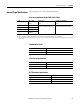
Travel
Travel Length mm (in.)
Shortest 60 (2.36)
Increments 60 (2.36)
Longest 1680 (66.14)