
Installation Owner's manual

74 Rockwell Automation Publication CHPS-UM001D-EN-P - July 2014
Appendix A Specifications and Dimensions
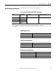
Encoder Specifications
Maximum Velocity for Allen-Bradley Drives
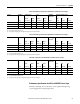
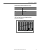
Table 10 - Maximum Velocity for 150 mm frame size CHPS-Series Linear Stages with Allen-Bradley
Drives
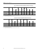
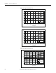
Table 11 - Maximum Velocity for 200 and 250 mm frame size CHPS-Series Linear Stages with
Allen-Bradley Drives
Type Signal Specification
Power Supply 5V DC ±5%
Digital A/B/Index RS422 Differential Line Driver
Analog Sine/Cosine 0.6…1.2V p-p Differential Analog
Integral Index Mark Differential Pulse 0.8…1.3V p-p
IMPORTANT
Contact Application Engineering for third party drives and controllers. The controls
need to meet a minimum recommended counter clock frequency that varies with
encoder type and resolution and required peak speed.
Incremental Encoder Option Maximum Velocity
Digital
Resolution
Sine/Cosine
Period
Velocity,
max
Ultra™ 3000 and
Ultra5000 Drives
Kinetix 2000 and
Kinetix 6500 Drives
Kinetix 6000
Drive
Kinetix 300
Drive
μm/count μm m/s m/s m/s m/s m/s
1 — 5.0 4.0 4.0 1.5 2.0
0.5 — 3.0 2.0 2.0 0.7 —
0.1 — 0.7 0.5 — — —
— 20 4.0 2.0 2.0 2.0 —
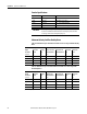
Incremental Encoder Option Maximum Velocity
Digital
Resolution
Sine/Cosine
Period
Velocity,
max
Ulta3000 and
Ultra5000 Drives
Kinetix 2000 and
Kinetix 6500 Drives
Kinetix 6000
Drive
Kinetix 300
Drive
μm/count μm m/s m/s m/s m/s m/s
1 — 5.0 4.0 4.0 1.5 2.0
0.5 — 3.0 2.0 2.0 0.7 —
0.1 — 0.7 0.5 0.5
(1)
——
— 20 4.0 2.0 2.0 2.0 —
(1) LC motor option only.