
Installation Owner's manual


Rockwell Automation Publication CHPS-UM001D-EN-P - July 2014 55
Chapter 8
Troubleshooting
Before You Begin
The following test equipment is required:
• Ohm meter
• Two-channel storage oscilloscope
PTC Thermal Signal
At ambient room temperature, approximately 25 °C (77 °F), check that the
resistance measurement between PTC Temp+ and Common (pins 13 and 14,
respectively) on the feedback connector is
≤ 750 Ω.
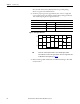
The table lists increase in resistance at higher temperatures outside the normal
operating temperature envelope.
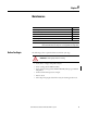
Table 5 - PTC Thermistor Signal Characteristics
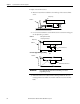
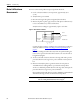
Hall Effect Module
Use this procedure to verify the Hall Effect module is operating properly.
1. With drive power OFF, verify the Hall circuit is properly connected to the
drive by using stage and drive interface wiring specifications.
2. Disconnect stage power leads from the drive.
3. Apply power to the Hall device by setting the drive control power to ON.
4. Use an oscilloscope to check waveforms at S1, S2 and S3 at the feedback
connector.
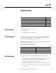
Topic Page
Before You Begin 55
PTC Thermal Signal 55
Hall Effect Module 55
Hall to Back EMF Phasing 57
Motor Coil Resistance Measurements 58
Temperature °C (°F) Resistance in Ohms
Up to 100 (212) ≤ 750
Up to 105 (221) ≤ 7500
Up to 110 (230) ≥ 10,000