
Installation Owner's manual

Rockwell Automation Publication CHPS-UM001D-EN-P - July 2014 45
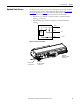
Connecting the Stage Chapter 6
Sine/Cos Encoder Output
Signals
Use the following information to connect a stage with a Sine/Cosine Encoder
option to a drive or controller that processes sine/cosine position feedback.
The sine/cos encoder amplitude is 0.90V p-p minimum up to 2 meters per
second. 0.60V p-p up to 4 meters per second.
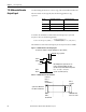
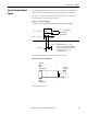
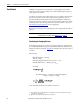
Figure 13 - Sine/Cos Encoder Timing
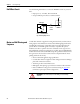
Recommended termination = 120 Ω resistors, V0, V1, V2.
Figure 14 - Sine/Cos Encoder Termination
(1) Total termination resistance in ohms.
Incremental 2 channels V
1
and V
2
dierential sinusoids in quadrature (90° phase shifted)
Dierential pulse V
0
- 18°…108°
Duration 126° (electrical) Repeatability of
position (uni-directional) is maintained if
temperature is 15…35 °C and
speed is <250 mm/s
Reference
20 μm
90°
0.6 …1.2V p-p with green
LED indication and
120 Ω termination
108º
-18º
0º
Sine = (V
1
+)-(V
1
-)
Cosine = (V
2
+)-(V
2
-)
0.8…1.2V p-p
(V
0
+)-(V
0
-)
Readhead
Drive or
Controller
120 Ω
(1)
ENC A +,
ENC B +,
& Index Mark +
ENC A -,
ENC B -,
& Index Mark -