
Installation Owner's manual

44 Rockwell Automation Publication CHPS-UM001D-EN-P - July 2014
Chapter 6 Connecting the Stage
TTL Differential Encoder
Output Signal
Use the following information to connect a stage with a TTL Differential Encoder.
The incremental encoder typically have the following quadrature edge
separation.
To calculate the minimum recommended counter frequency for 1
μm and
0.5
μm encoders, use the following formula.
The minimum recommend counter frequency for the 0.1
μm encoder is 12 MHz.
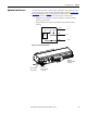
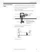
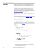
Figure 11 - TTL Differential Encoder Timing Diagram
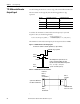
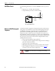
Figure 12 - TTL Differential Encoder Termination
(1) Total termination resistance in ohms.
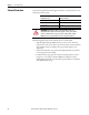
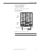
Encoder Typical Edge Separation @ Maximum Velocity
(1)
(1) Speeds based on 3 m maximum cable length and a minimum readhead input of 5V.
μm ns m/s
1 100 5
0.5 90 3
0.1 90 0.7
Counter clock frequency (MHz)
encoder velocity m s⁄()
resolution μm()
-------------- ---------------------------------------- -----
4× (safety factor)=
Incremental 2 channels A and B in quadrature (90° phase shifted)
Quadrature edge separation
Reference
Index Mark pulse in synchronised to one
position count. Repeatability of position
(uni-directional) is maintained if temperature
is 15…35 °C (59…95 °F) and
speed is <250 mm/s (9.8 in./s).
ENC A+
ENC B+
Index
Mark +
Drive or
Controller
Standard RS422A
line receive circuit
Square wave dierential
line driver to EIA RS422A
120 Ω
(1)
Readhead
ENC A +,
ENC B +,
& Index Mark +
ENC A -,
ENC B -,
& Index Mark -