
Installation Owner's manual

42 Rockwell Automation Publication CHPS-UM001D-EN-P - July 2014
Chapter 6 Connecting the Stage
Thermal Protection
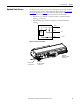
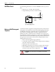
Connect the stage PTC thermistor signal to the drive or control system to create
a thermal protection system.
The following thermal protection methods are also recommended.
• Typically digital drives use RMS current protection and or estimated
temperature vs. time (I
2
T) software protection schemes. Activated and set
these available features according to the stage model ratings for your
application.
• Set the maximum value of ± peak-current-magnitude limits of your drive
to the stage’s peak-current rating.
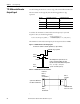
• For drives without stage protection features, install stage fuses (current
rating not to exceed stage continuous RMS) according to local and
National Electrical Code. Uses time-delay type fuses that are rated for the
drive PWM output voltage.
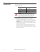
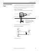
PTC Thermistor Signal Characteristics
Temperature °C (°F) Resistance in Ohms
Up to 100 (212) ≤ 750
Up to 105 (221) ≤ 7500
Up to 110 (221) ≥ 10,000
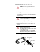
ATTENTION: PTC thermistor supplies a signal that indicates the stage
temperature limit condition. Connect this signal to control system or drive
system so it shuts down the stage power upon reaching a limit condition.
Multiple levels of stage thermal protection are strongly recommend.