
Installation Owner's manual

36 Rockwell Automation Publication CHPS-UM001D-EN-P - July 2014
Chapter 5 Connector Data
Flying Leads
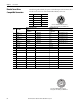
The following tables identify the power and feedback pinouts for flying lead this
option lest you to use your own connectors.
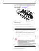
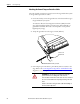
ATTENTION: Disconnect input power supply before installing or servicing stage
Stage lead connections can short and cause damage or injury if not well secured
and insulated.
Insulate the connections, equal to or better than the insulation on the supply
conductors.
Properly ground the stage as described in the drive manual.
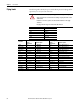
Color Signal
Red U (A) phase
White V (B) phase
Black W (C) phase
Green/Yellow Ground
Shield Cable Shield
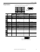
Color Wire
With Incremental Encoder With Analog Encoder
Signal
Designations
Signal Description
Signal
Designations
Signal Description
Yellow A+ TTL - Differential Sin+ Analog - Differential 1V p-p
White/Yellow A- TTL - Differential Sin- Analog - Differential 1V p-p
Brown B+ TTL - Differential Cos+ Analog - Differential 1V p-p
White/Brown B- TTL - Differential Cos- Analog - Differential 1V p-p
Violet Index Mark+ TTL - Differential Index+ Differential Pulse 1V p-p
White/Violet Index Mark- TTL - Differential Index- Differential Pulse 1V p-p
Red +5V Encoder and Hall Sensor Power +5V Encoder and Hall Sensor Power
White/Red +5V Encoder and Hall Sensor Power +5V Encoder and Hall Sensor Power
Black Common — Common —
White/Black Common — Common —
Green PTC Temp+
(1)
PTC Thermistor PTC Temp+
(1)
PTC Thermistor
White/Green S1 TTL - Trapezoidal Hall S1 TTL - Trapezoidal Hall
Blue S2 TTL - Trapezoidal Hall S2 TTL - Trapezoidal Hall
White/Blue S3 TTL - Trapezoidal Hall S3 TTL - Trapezoidal Hall
Green/Yellow Shield — Shield —
(1) PTC Temp- is connected to Common.