
Installation Owner's manual

Rockwell Automation Publication CHPS-UM001D-EN-P - July 2014 35
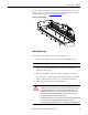
Connector Data Chapter 5
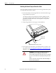
D-Type Connectors
The following tables identify the power and feedback pinouts for D-shell
connectors that enable custom cables to be used.
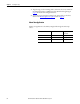
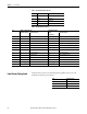
Pin Color Signal
A1 Red U (A) phase
A2 White V (B) phase
A3 Black W (C) phase
A4 Green/Yellow Ground
Case Shield Cable Shield
M
A1
A2 A3
A4
Positronic P/N CBD9W4M20000-1702.0
Mating Connector:
Positronic P/N CBD9W4F20000-1701.0
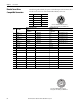
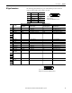
Pin Color Wire
With Incremental Encoder With Analog Encoder
Signal
Designations
Signal Description Signal Designations Signal Description
1 Yellow A+ TTL - Differential Sin+ Analog Differential 1V p-p
2 Brown B+ TTL - Differential Cos+ Analog Differential 1V p-p
3 Violet Index Mark + TTL - Differential Index+ Differential Pulse 1V p-p
4 White/Red +5V DC Encoder and Hall Sensor Power +5V DC Encoder and Hall Sensor Power
5Reserved — — — —
6
7
8
9 White/Green S1 TTL - Trapezoidal Hall S1 TTL - Trapezoidal Hall
10 Green PTC Temp+
(1)
PTC Thermistor PTC Temp+* PTC Thermistor
11 Reserved — — — —
12 White Blue S3 TTL - Trapezoidal Hall S3 TTL - Trapezoidal Hall
13 Green/Yellow Shield — Shield
14 White/Yellow A- TTL - Differential Sin- Analog Differential 1V p-p
15 White/Brown B- TTL - Differential Cos- Analog Differential 1V p-p
16 White/Violet Index Mark- TTL - Differential Index- Differential Pulse 1V p-p
17 Black,
White/Black
Common — Common —
18 Reserved — — — —
19
20
21
22 Blue S2 TTL - Trapezoidal Hall S2 TTL - Trapezoidal Hall
23 Reserved — — — —
24
25
(1) PTC Temp- is connected to Common.
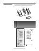
M
1
1
14
25
13
Connector Part Number AMP P/N 207464-2
Mating Connector Part Number AMP P/N 5205207-1