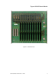
Triguard SC300E Chassis Models Chassis Models Issue 4 October 2005 INTRODUCTION PURPOSE The chassis accommodates the various system modules and their power supplies. It comprises a 9U standard 19 inch rack mounting module cage and a printed circuit backplane. NOTE A ‘U’ is one unit and measures 44mm (1.75 inches). The ‘U’ is an industry standard and used by equipment cabinet manufacturers as a measure of height for rack systems.
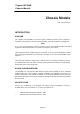
Triguard SC300E Figure 1-1. SC300E Architecture As c an be seen from the block diagram in Figure 1-1 a SC300E system has a fully triplicated architecture from input modules to output modules. All SC300E input and output modules interface to three isolated I/O communications buses, each being controlled by one of the three main processor modules. At the input modules, field signals are filtered and then split, via isolating circuitry, into three identical, signal processing paths.
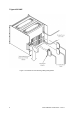
Triguard SC300E Chassis Models All input and output modules can be configured to use a hot spare partner module. In the event of failure of the main I/O module its duty is taken over (manually or automatically) by the hot spare partner, allowing repairs to be effected. HARDWARE The system circuits are accommodated mainly within a number of identical box chassis which can be individually configured and interconnected to form the required system layout.
Triguard SC300E Figure 1-3.
Triguard SC300E Chassis Models Figure 1-4.
Triguard SC300E Figure 1-5.
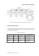
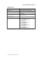
Triguard SC300E Chassis Models Figure 1-6. Chassis interconnections for system layout with remote chassis CHASSIS TECHNICAL DATA The chassis variants covered by this document differ only in the basic equipment (excluding I/O modules) fitted into them and whether they can be powered from 110/230Vac or 24Vdc. Table 1-1 lists the details of each variant. Table 1-1.
Triguard SC300E Table 1-1.
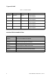
Triguard SC300E Chassis Models SPECIFICATION Model See under “Weight as supplied” Construction 2mm aluminium alloy to BS5251(NS4)H4 Finish Anodised Cooling Convection cooled via ventilation holes in top and bottom surfaces Overall size (mm) Overall size (inches) 483W x 400H x 486D 19W x 15.8H x 19.2D Weight empty 8.6 kg Weight as supplied (no I/O modules) Main chassis: 110/230Vac (CXP10A11): 17.2 kg 24Vdc (CXP10D24): 17.2 kg Extension chassis: 110/230Vac (CXB10A11): 15.
Triguard SC300E ENVIRONMENTAL SPECIFICATION The maximum ambient temperature measured at the hottest point within the Triguard system shall not be greater than 60 degrees centigrade. Temperature operating: +5°C to +60°C Temperature storage: -25°C to +70°C Humidity: 5% to 95% non-condensing at ambient < 40°C EMC/RFI Immunity: Tested and certified to IEC 1131-Part 2 1994 Vibration/Shock: Tested and certified to IEC 1131-Part 2 1994 Certification: General Certification:Ref.
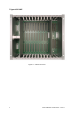
Triguard SC300E Chassis Models TECHNICAL DESCRIPTION PHYSICAL The chassis box has two side plates with flanges to enable 19 inch rack mounting, they are bolted to top and bottom plates and to a multilayer printed board backplane that carries all module connections and interconnections. The top and bottom plates are perforated to facilitate cooling.
Triguard SC300E Table 2-1. Chassis/Module mechanical coding configurations Module mechanical coding positions Upper coding block Lower coding block Nomenclature 1 2 3 4 MDI32BIS (3-2-0) x x x x MDI16BNS x x x x MDI32FIS x x x MDO32BNS x x x MDO16FNS x x x MAD32LAD/MAD x x MAO04NND x x MHB44IND x x MSR04XI X x MDI32BIS (3-2-1) x x 1 2 3 4 x x x x x x x x x x x The coding positions shown can be used for both module and chassis settings.
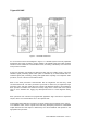
Triguard SC300E Chassis Models Power supply slots 1 and 2 Upper coding blocks I/O module slots 1 to 10 Processor slots A, B,C AC PSU stud Slot for PSU 1 Slot for PSU 2 PSU guide pin Module guides Lower coding blocks Figure 2-1.
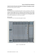
Triguard SC300E BACKPLANE Figure 2-2. Rear view of chassis showing backplane detail The backplane is a multilayer printed circuit board that forms the rear plate of the box chassis and carries all the interconnections and input/output connectors.
Triguard SC300E Chassis Models • A ‘rear plug up’ expansion connector for each bus • A rear mounted diagnostic port for each processor • Polarised power input connectors • PSU status output connectors • Spade terminal earth connectors for optional chassis earthing • Spade terminal earths for optional Field I/O cable earthing Many of the above functions are allocated specific areas with alphabetic references on the backplane as shown in Table 2-2. Table 2-2.
Triguard SC300E ‘X’ signifies a pin fitted Figure 2-3.
Triguard SC300E Chassis Models Areas ‘b’ and ‘c’ - Field I/O The connectors in areas ‘b’ and ‘c’ are the field connectors for the I/O modules and, apart from pin 1c which is always chassis earth, the pin functions depend upon the module in use in each slot. Refer to the User Manual for the module for details of the pin functions. Figure 2-3 shows the layout of the connectors; ‘x’ signifies a pin available for use, ‘o’ signifies that the pin is not fitted. None of the pins in the middle column are fitted.
Triguard SC300E UNIT ID ‘X’ signifies a pin fitted Figure 2-5.
Triguard SC300E Chassis Models Figure 2-6.
Triguard SC300E Area ‘e’ - Processor expansion bus Connectors in area ‘e’ provide the means to extend the system bus to extension chassis. If more than one extension chassis is to be linked in, an Expansion Bus Adaptor must be fitted to these connectors (Ref. Section 1.6, Associated documentation). ‘X’ signifies a pin fitted Figure 2-7.
Triguard SC300E Chassis Models Area ‘g’ - Processor diagnostic ports The connectors (26 pin IDC) in area ‘g’ are diagnostic ports, one for each processor; their signals are the same as those available at the diagnostic ports on the processor front panels (refer to the MPP User Manual 008-5100). Areas ‘h’ - Power supply unit connectors WARNING Do not remove the clear plastic covers from the backplane areas ‘h’, the power supply terminations they are protecting may carry lethal voltages.
Triguard SC300E Figure 2-8. PSU Alarm connectors Areas ‘k’ - Power input Each Area ‘k’ contains the Power Input connector (Figure 2-9) for the related PSU, the same input connector, a 9-way MATE-N-LOK, can be used for either ac or dc power supplies depending upon which type of PSU is fitted. Figure 2-9. Power input connectors EARTHING The chassis metalwork is extensively and efficiently earthed to the Power Input earth via the backplane track and the earthing pads on the front of the backplane.
Triguard SC300E Chassis Models SERVICING SCOPE No servicing is necessary. WARNING Do not remove the clear plastic covers from the backplane areas ‘h’, the power supply terminations they are protecting may carry lethal voltages Chassis repair is by unit replacement. A faulty chassis is not repairable in the field, it should be replaced by a new unit and returned for repair. SERVICE SUPPORT SPARE PARTS Spare parts and technical advice can be obtained from your local area office.