The information in this user's manual is subject to change without notice. DANGER ONLY QUALIFIED ELECTRICAL PERSONNEL FAMILIAR WITH THE CONSTRUCTION AND OPERATION OF THIS EQUIPMENT AND THE HAZARDS INVOLVED SHOULD INSTALL, ADJUST, OPERATE, OR SERVICE THIS EQUIPMENT. READ AND UNDERSTAND THIS MANUAL AND OTHER APPLICABLE MANUALS IN THEIR ENTIRETY BEFORE PROCEEDING. FAILURE TO OBSERVE THIS PRECAUTION COULD RESULT IN SEVERE BODILY INJURY OR LOSS OF LIFE.
Preface AutoMax Ladder Editor Feature Overview The AutoMax Ladder Editor ships as part of the AutoMax Programming Executive. It can be run from within the Executive or as a standĆalone application for offline programming only. The Editor provides these features to help you create your ladder programs: More easily view and work with rungs in the same program or in different programs.
More easily edit online programs. When editing an online program you can: Identify inserted, deleted, or modified rungs View the original program while you are editing an online version of the same program Monitor and modify timer and counter preset values Test online edits before permanently downloading them to the Processor Set, force, and unforce variables from within the Editor Where to Find More Information This instruction manual describes the AutoMax Enhanced Ladder Editor.
Table of Contents 1.0 Getting Familiar with the Editor . . . . . . . . . . . . . . . . . . . . . . . . . . . . . . 1Ć1 1.1 Overview of the AutoMax Ladder Editor Window . . . . . . . . . . . . . 1Ć1 1.2 Opening Programs . . . . . . . . . . . . . . . . . . . . . . . . . . . . . . . . . . . . . . . 1Ć2 1.3 Closing Programs . . . . . . . . . . . . . . . . . . . . . . . . . . . . . . . . . . . . . . . 1Ć3 1.4 Saving Programs . . . . . . . . . . . . . . . . . . . . . . . . . . . . . . . . . . . . . . . . 1Ć3 1.
Inserting and Deleting Page Breaks . . . . . . . . . . . . . . . . . . . . . . . . Printing a Range of Rungs . . . . . . . . . . . . . . . . . . . . . . . . . . . . . . . . Displaying and Printing Coils as RightĆJustified . . . . . . . . . . . . . . Printing Multiple Copies of Programs . . . . . . . . . . . . . . . . . . . . . . . 3Ć7 3Ć7 3Ć8 3Ć8 Verifying Programs . . . . . . . . . . . . . . . . . . . . . . . . . . . . . . . . . . . . . . . . . 4.1 Creating a Verify Error Log File . . . . . . . . . . . .
Appendices Appendix A Toolbars, Palettes, and the Status Bar . . . . . . . . . . . . . . . . . . . . . . . . . AĆ1 Appendix B Keyboard Shortcuts . . . . . . . . . . . . . . . . . . . . . . . . . . . . . . . . . . . . . . . . . BĆ1 Appendix C Using the PreĆDefined (Reserved) Ladder Language Variables . . . . CĆ1 Appendix D Online Editing Memory Limits . . . . . . . . . . . . . . . . . . . . . . . . . . . . . . . . . DĆ1 Appendix E Rung Execution Order . . . . . . . . . . . . . . . . . . . . . . . . . . . . .
fafadfdfdasfdsfdsdsdfdsfdsfdsfsdfdsa afdfdsfdsfdfdsfdsfsadfda asfdfaddfdd
1.0 Getting Familiar with the Editor This section describes some basic information to help you become familiar with the Editor. 1.
Program Windows: Presents the open program(s).
program. To convert the program, choose Yes. For more information, see Appendix F. You can have at most 15 unique offline programs opened at one time. 1.3 Closing Programs Close the active program with the Close command. The Editor stays active and any other open programs stay open. The Editor prompts you to save any changes to open programs before closing. To close a ladder program 1.4 Step 1. From the File menu or Program Control Menu, choose Close. Step 2.
1.5 Saving Programs Automatically As You Work To make sure that you do not lose work, you can use the Automatic Save Every feature to save your offline ladder programs at a specified intervalāĊāfor example, every ten minutes. Specify whether you want your programs to be saved automatically and the time interval to use within the General Options tab. Files that are saved automatically are stored in the same directory as the original ladder program and under the same name.
1.7 Editing Different Parts of the Same Program Using Split Windows A program window may be split into two horizontal panes. Any editing done in one pane is reflected in the other. Each pane can be scrolled independently using its own vertical scroll bar. To view different parts of the same program using the Split command Step 1. From the Window menu, choose Split. The cursor turns into a split pointer, a combination up arrow and down arrow. Step 2.
To edit multiple ladder programs from the Editor Step 1. From the File menu, open all the programs you want to edit. Step 2. From the Window menu, select Tile or Cascade. All nonĆminimized programs are arranged within the Ladder Editor window. Or, use the mouse to arrange the windows on the desktop. Step 3. Click on the program window to make it active before editing the program. Tip To switch among the programs you are editing, press CTRL+F6. 1.
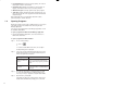
1.10 About Program Properties The Program Properties dialog box contains three tabs: Use this tab: For: Program Info viewing information about the program Scan Info defining how the program should be scanned and the program's scan time. Error Log viewing the online error log To access Program Properties from the File menu Step 1. Make sure no rung or instruction is selected. Step 2. From the File menu, choose Properties. The Program Properties dialog box is displayed.
Hardware events are generated by an external condition. These AutoMax modules can set a hardware event: UDC module (57652) Pulse Tach Input module (57C421) Resolver Input module (57C411) 2ĆChannel Analog Input module (57C409) 32ĆBit Digital Input module (57C419) However, hardware events cannot be used on the AutoMax PC3000. See a module's instruction manual for information about interrupts. For more information, see section 1.11.2. Software events are flags generated by other programs.
You can specify a timeout for the hardware event. This lets you specify the maximum amount of time in ticks that can pass before the hardware event occurs. You can use a timeout as a safeguard in case something happens to the module you are using to generate the hardware event. If the event does not occur before the timeout time, a rack STOP ALL error occurs. To specify a hardware event Step 1. Access Program Properties.
1.12 Step 4. Select Software as the Event Type. Step 5. In the Name field, type the name of the software event that will trigger the program's execution. Step 6. Click OK to accept the changes. Running and Stopping Ladder Programs Use the Online Task Manager to place a program into run or to stop a program. If you are editing online, you must pause the Editor before you can access the Online Task Manager, since they both share the same communication channel. See Pausing the Editor," section 5.
2.0 Editing Programs This chapter describes how to use the Editor to edit programs offline. See chapter 5 for information about editing programs online. 2.1 Starting a Rung The first step in entering ladder logic is inserting the first instruction in the rung. Place the first instruction of a rung against the left power rail. All rungs are aligned against the left power rail. To start a rung Step 1. Click on the Ladder Language toolbar button that accesses the group of instructions you need.
2.1.1 Defining the Horizontal and Vertical Grid Limits Per Rung You can define limits for the size of the grid used by the Editor to lay out each rung. This lets you make sure that your program printouts fit on your preferred page size without the rungs being split up. Relay instructions occupy a grid space of 1 x 1. More complex instructions occupy at least 3 units horizontally by 2 to 8 units vertically.
If rung numbers are not displayed, you can still select the rung by clicking in the rung status area next to the rung. Step 1. Think of the rung you want as being enclosed in a box, and position the pointer on the white space at either the top or bottom corners." Step 2. Press the left mouse button. The cursor changes to +. Step 3. Draw a selection box around the rung by moving the mouse diagonally across the rung.
2.3 Entering Rung Descriptions Rung descriptions help you document the program's logic so that others can understand the function of each rung and help make troubleshooting easier. Rung descriptions can contain a maximum of 16 lines, with each line containing a maximum of 80 characters of text. You must turn on rung descriptions to view them in the program. To enter a rung description in the program window Step 1. Make sure Rung Descriptions are turned on. Step 2.
2.4 Inserting Instructions into a Rung Build a rung by using the mouse to drag and drop instructions from an instruction palette and connect them together by drawing wires. The program area is like a blank canvasāĊāyou drag instructions from the instruction palettes and drop them in the program area. But first, you must start a rung by dragging an instruction from an instruction palette and dropping it very near the left power rail.
2.5 Connecting Instructions (Drawing Wires) Connect instructions when you want to create branches (parallel logic) or to connect two or more instructions together that were placed too far apart for them to connect automatically. Connect instructions by drawing wires. You can use the grid markers to help you determine where instructions will be placed and where you can draw wires. To connect instructions Step 1. Place the cursor near a connection point for an instruction.
2.7 Selecting Instructions Before you can copy, cut, clear, or move an instruction, you must first select it. To select an instruction Click on any part of the instruction such as the instruction itself, a variable used in the instruction, or the description. or Draw a selection box around the instruction. A selection box is a dottedĆline rectangle like this: A selected instruction looks like this: To select an instruction by drawing a selection box Step 1.
To select multiple, contiguous instructions by drawing a selection box Draw a selection box to encompass the instructions you want to select. You can only select instructions that belong to the same rung. or Step 1. Select an instruction. Step 2. While pressing SHIFT, place the mouse pointer on the selected instruction and press the left mouse button. A selection box appears. Step 3. While holding down the mouse button, drag the selection box to encompass the instructions that you want to select.
To access Instruction Properties from the popĆup menu Step 1. Point to the instruction, and press the right mouse button. Step 2. From the popĆup menu, choose Properties. The Instruction Properties dialog box is displayed. To display the variable properties tab, choose Variables. To display information about the instructions, choose Instruction Info. Quickly toggle between the two tabs by using CTRL+TAB. 2.
Tip You can also access the Instruction Info tab from the popĆup menu. Point to the instruction that you want to change, press the right mouse button, and choose Properties from the popĆup menu. Tip You can also change the information about the variables used in the instruction. Simply choose the Variables tab or press CTRL+TAB to display the Variable Properties. Tip To select the instruction and access the popĆup menu, place the mouse pointer over the instruction and click the right mouse button. 2.
Tip If the variable has not been used before, a default data type and scope is automatically assigned. If the variable is an array, the maximum array index defaults to the value you entered as the element of the variable. For example, if you entered part[5] the value of 5 would be entered into the Maximum Array Index field of the Variable Properties. If the elementĆindex of an array is a variable, the Maximum Array Index field contains a value of 1.
To enter a variable description by using the Variables tab in the Instruction Properties dialog box Step 1. Select the instruction that contains the variables you want to document. Step 2. From the File menu, choose Properties. The Instruction Property dialog box is displayed. Step 3. Choose the Variables tab. The Variables Properties box is displayed. Step 4. In the Name list box, choose the variable you want to document. Step 5. Click on the Description field, and type in the description.
To scroll through the available variable names that match the character(s) you have typed To advance, press CTRL and the down arrow. To move backward through the matching variable names, press CTRL and the up arrow. The Variable SmartĆMatching option provides matches to each part of an elementĆindexed and/or bitĆindexed variable. Enter the elementĆindex or bitĆindex delimiter and the first letter or letters of the element or bit name. Then, scroll through the variable name choices offered.
To change the data type for a variable Step 1. Select the instruction containing the variable whose data type you want to change. Step 2. From the File menu or the popĆup menu, choose Properties. The Instruction Properties dialog box is displayed. Step 3. Choose the Variables tab. The Variable Properties tab is displayed. Step 4. If the name of the variable you want is not displayed in the Name field, use the list box to scroll through a list and choose it.
To change a variable's scope Step 1. Select the instruction containing the variable whose scope you want to change. Step 2. Access its Instruction Properties by choosing Properties from either the File menu or the popĆup menu. The Instruction Properties dialog box is displayed. Step 3. Choose the Variables tab. The Variable Properties tab is displayed. Step 4. If the name of the variable you want is not displayed in the Name field, use the list box to scroll through and choose it.
fafadfdfdasfdsfdsdsdfdsfdsfdsfsdfdsa afdfdsfdsfdfdsfdsfsadfda asfdfaddfdd
3.0 Printing Programs Print a program to mark up or maintain a paper record of it. You can print: an entire program or a range of rungs rung descriptions only rung descriptions variable descriptions instruction crossĆreference program crossĆreference multiple copies of a program The ladder diagram prints out on the default printer you have defined for the computer. Make sure that this printer is connected and the proper print driver is installed. See the Windows 95 documentation for more information.
Step 3. Step 4. Use this table to help you with your next steps: To: Do the following: print all the rungs in the program In the Print Range box, select All. print only the rungs within a selected range In the Print Range box, select Selected Rungs. print more than one copy of the program Enter or select the number of copies using Copies. define page margins Choose Page Setup. define other print options Choose Options. When you are ready to print the program, choose OK.
When you print the Program (task) crossĆreference, it prints at the end of the printout and is printed for the entire program, even if you selected only a range of rungs to print. The program crossĆreference contains the following items: variable name table This table includes each variable used in the task, its data type, the instruction and rung where it is used, its I/O type, the hardware address, its description, and the line crossĆreference.
3.2 Setting Print Options You can choose the type of information to print on your programs' printout. Choose to print or not to print the following: To print: Choose: Result: a program's ladder logic rungs Rungs The rungs are printed. any description assigned to rung Rung Descriptions The rung descriptions print above the rung. The line length is the same as the page width. The description is truncated if it is longer than the page width.
To define the print options Step 1. Access the Print Option Tab by choosing: Options from the Tools menu and then the Print Tab or the Options button on the Print dialog box Step 2. Choose the items you wish to print when you print a program. Your choices are listed within the Print What group box. Step 3. Click OK. The options you choose apply to any program that you print. Tip To return to using the default print options, select the Use Defaults button. 3.
3.4 How a Rung Is Printed To Fit on a Single Page The Editor prints a rung (including rung descriptions, variable names and descriptions, and instruction crossĆreferences) on one page. If a rung or an instruction block cannot be printed entirely on one page and there are other rungs on the page, the Editor forces the logic to a new page.
Wires and instructions can also be split. See the following example: 3.5 Inserting and Deleting Page Breaks Use a page break to paginate a program's printout for a cleaner look. To insert or delete a page break Step 1. If you are inserting a page break, select a program object with which you want to start a new page. If you are deleting a page break, select a program object that starts a new page. Step 2. From the Insert menu, choose Page Break.
3.7 Displaying and Printing Coils as RightĆJustified Use the Right Justify Coils after Verify feature to automatically move coils to the right side of the printout so that you can more easily read your program. If coils are not blocked by another instruction, the Editor aligns them against the first vertical page break. Coils that already extend past this page break are moved left and up. (They are not moved to the next page break.) To display and print programs with rightĆjustified coils Step 1.
4.0 Verifying Programs Use the Verify command to help debug your ladder program. During the verification process, the Editor checks your program and notifies you of any errors that would prevent the program from running. If you choose, the Editor can report less serious issues, called warnings. See section 4.3 for more information. The error and warning messages also include information about the rung and grid location in which the error or warning occurred.
4.1 Creating a Verify Error Log File Select the Generate Log File option in the General Options tab to create a log file on disk containing the same error, warning, and status messages as the Verify Output window. This file is stored in the same path as the program with the same name but with a .LOG extension. It can be opened and viewed using a text editor like WordPad. The Editor generates a log file for each program by default. To create a verify log file Step 1. From the Tools menu, choose Options.
4.3 Specifying Whether To Include Warning Messages When Verifying Programs Select the Ignore Warnings option in the General tab options from the Tools menu to prevent verify warnings from being displayed in the Verify Output window and verify log file (if the log file is generated). Verify error messages are always displayed in the output window and log file. By default, the Editor includes verify warning messages in the output window and log file of offline programs that you verify.
fafadfdfdasfdsfdsdsdfdsfdsfdsfsdfdsa afdfdsfdsfdfdsfdsfsadfda asfdfaddfdd
5.0 Editing Programs Online Editing a program online lets you modify ladder logic and the initial values of variables as well as set, force, and unforce variables. You can be connected to a Processor via a serial connection or a PC Link interface connection. If you are connected via the PC Link module, you can have multiple online programs from different networked racks opened simultaneously.
About Accepting and Downloading Your Changes When you set, force, unforce, or change a variable's initial value, the change takes effect immediately in the online program. Other changes such as adding, deleting, or modifying a rung must be accepted before the change takes effect. You can accept one or all rungs that have been added, deleted, or changed. Accept changes that you want to download to the Processor.
Test mode The program is actively executing rungs, but the changes made to an online program are not permanently installed in the Processor. You can test the changes you made to an online program. The text Test Mode" appears after the file name in the window's title bar. See Testing Programs (Test Mode)," section 5.8, for more information. Paused When the Editor is paused, the programs continue to run in the Processor, but their display in the program window is not updated.
5.2 Monitoring an Online Ladder Program Before you can edit an online program, you must open it using the Monitor PC Program command from the Online menu. You access this command from the Editor, Task Manager, or System Configurator. To monitor an online ladder program Step 1. Close the Online Task Manager application if it is running. The Online Task Manager uses the same online connection as an opened online program. Both applications cannot be accessed at the same time. Step 2.
5.3 Pausing the Editor Because the Online Task Manager and online programs in the Editor use the same communication channel, you must place the Editor in the Paused state before you can use the Online Task Manager. The programs continue to run in the Processor, but their display in a program window is not updated. IMPORTANT Before pausing the Editor's online program windows, you might want to commit any pending changes.
5.5 Monitoring Data in an Online Program While a program is running online, the data is displayed as follows: Forced variables are highlighted in the Forced Variable color, defined via the Color Option tab of the Program Properties. Numeric values are displayed under the variable name. You can define the data display format using the Variable Properties tab for the variable but only in an offline program. A timer's elapsed value is displayed under the timer variable name.
To accept or reject changes made to an online program Step 1. When you are finished editing an online program, do one of the following: Choose Accept from the Online menu or Click on The first edited rung is highlighted and displayed along with the Accept Online Changes Dialog box. Step 2. From the Accept Online Changes dialog box, perform one of the following actions: Choose this button: To: Result: Approve the displayed rung. Accept The next edited rung is displayed for you to accept.
From the Commit Online Changes dialog box, you must choose how to download the online changes to the Processor. You can download the changes to the Processor by sending the changes to the Processor and either: immediately install the changes in the program by selecting Commit temporarily install the changes in the program by selecting Test Mode The changes are downloaded to the Processor as a group. To download changes made to an online program (commit) Step 1. Accept the changes to an online program.
5.8 Testing Programs (Test Mode) Selecting Test Mode from the Commit Online Changes dialog box places the program in the Test Mode state, which provides you with an opportunity to make sure that the changes you made work properly before you permanently install them in the Processor. Once a program is in Test Mode, you can: commit the online changes, which permanently installs the program in the Processor (see section 5.8.
5.8.2 Removing an Online Program from Test Mode If you want to continue making changes to an online program that is in Test Mode, you must first take it out of Test Mode. You can do this by using the Quit Test Mode command from the Online menu. Taking a program out of Test Mode removes the changes from the Processor. The modified rungs are no longer running on the Processor; the original rungs are now executing.
All pending changes are removed from the program. If the program was in Test Mode, it is removed from this mode. 5.9 About How Changes Made to Online Programs Are Verified Once you commit any online changes after accepting the rungs, the Editor verifies the changes before they are downloaded to the Processor. The changes are verified using the same rules that are used for offline programs. All accepted online changes must be successfully verified before they are installed into a Processor.
5.10 Viewing an Online Program as It Looked Before It Was Edited While you are editing an online program and before you commit any online changes, you can view the same program as it appeared before you began making modifications. The Editor displays the original program in a separate window. The text (Original Program)" printed before the file name in the window's title bar helps you identify the original program from the edited version.
5.11 Capturing the State of Logic in an Online Program While monitoring a program, you can freeze or capture the power flow of a given rung using the Capture Trigger command from the Online menu. When the trigger is activated (becomes true), the state of the rung is captured and displayed. The rung's power flow information is not updated on the computer; however, it continues to run on the Processor. The Editor obtains trigger information from the Processor.
5.11.1 Capturing the State of Logic Based on a Coil Becoming True You can freeze the power flow of a rung based on its upperĆrightĆmost coil turning on (becoming true). You use the Coil On command from the Capture Trigger menu. When a rung has a Coil On trigger set, the rung is marked with a letter o" in the rung status area. To set a Coil On trigger Step 1. Select the rung or at least one instruction in the rung for which you want to set a trigger. See Selecting Rungs," section 2.
5.11.3 Capturing the State of Logic Based on a Rung Error You can freeze the power flow of a rung based on a runĆtime error occurring within the rung. RunĆtime errors may be those caused by an instruction. You use the Rung Error command from the Capture Trigger menu. When a rung has a Rung Error trigger set, the rung is marked with a letter e" in the rung status area. To set a Rung Error trigger Step 1. Select the rung or at least one instruction in the rung for which you want to set a trigger.
5.11.6 Clearing a Trigger You can remove a set trigger for a selected rung. Once the trigger is removed, the rung's status area returns to the state it was in prior to the trigger being set. To clear a trigger Step 1. Select the rung or at least one instruction in the rung containing the trigger you want to remove. See Selecting Rungs," section 2.2, or Selecting Instructions," section 2.7, for more information. Step 2. From the Online menu, select Capture Trigger.
About Setting a Variable To set a variable is to write a value to it that can be overĆwritten by an instruction in the same program, another program referencing the same variable, or an external device if the variable is mapped to an input. It is possible for a variable that is set to be overĆwritten on the next scan of the program. Forced values cannot be set. The Editor stores and displays up to 64 set variables for the current editing session.
When you select an offline program window or the Verify output window, the Set/Force/Unforce dialog box remains in its current state. 5.12.
Tip Selecting a variable from the Set Variables List fills the parameters within the Current Selection group box with the information for the variable. 5.12.2 Forcing Variables To force a variable is to write a value to it that cannot be overĆwritten by another program referencing the same variable. You can force any simple global variable in the configuration or any simple local variable present in a task that is loaded into the processor.
Tip To quickly fill in the Program and Variable Name field for a local variable you want to force, select the variable in the program before choosing the Set/Force/Unforce command. Selecting a global variable in the program before choosing the Set/Force/Unforce command fills in the Variable Name field in the Set/Force/Unforce dialog box. Tip Selecting a variable from the Force Variables List fills the parameters within the Current Selection group box with the information for the variable.
Variables grouped on one force page can be unforced at the same time. See Unforcing an Entire Force Page," section 5.12.7. Tip Selecting a variable from the Force Variables List fills the parameters within the Current Selection group box with the information for the variable. 5.12.4 About the Expanded Set/Force/Unforce Dialog Box Additional options not available in the basic Set/Force/Unforce Variables dialog box can be displayed by clicking More in the dialog box.
5.12.8 Step 2. From the Online menu, choose Set/Force/Unforce. The Set/Force/Unforce dialog box is displayed. Step 3. Click More. Step 4. In the expanded Set/Force/Unforce dialog box, use the Current Page field to choose the force page you want to unforce. Step 5. Click Unforce Page. The entire page is unforced. Testing If Variables in the Rack Are Forced Programs that are running can test if any variables in a rack are forced. The logic can access the reserved global variable FORCINGSTATUS@.
Appendix A Toolbars, Palettes, and the Status Bar A.1 About the Standard Toolbar The Standard toolbar contains shortcut buttons to many menu commands, such as cut, copy, paste, save, and print. It is located by default at the top edge of the program window, but you can move it to another location. By pausing the pointer over a toolbar button, you can display a brief description of the button.
As a shortcut for: Click this button: Quitting test mode Setting/Forcing/Unforcing a variable Showing the original copy of an online program Pausing an online program Accessing contextĆsensitive help A.2 About the Ladder Language Toolbar The Ladder Language toolbar provides access to the instruction palettes. Each button on the toolbar provides access to a certain group of instructions, such as relay or arrays.
A.3 About the Instruction Palettes You access an instruction palette by pointing and clicking on a Ladder Language toolbar button. Once the instruction palette is displayed, you drag instructions from it and insert them into a program. Instructions that perform similar operations are grouped together on a palette. For example, all relay instructions are grouped together on the relay palette. If you frequently use instructions from a particular palette, you can choose to keep it open.
Math Absolute Value (ABS) Subtract (SUB) Add (ADD) Logical AND (AND) Divide (DIV) Logical NOT (NOT) Modulo (MOD) Logical OR (OR) Multiply (MUL) Logical Exclusive XOR (XOR) Multiply Divide (MDV) Convert Co e Integer ege Data a a to o BCD C (TO BCD) (TO_BCD) Negate (NEG) Square Root (SQRT) Convert From BCD to Integer Data (BCD_TO) Unary Array Operations (AR1) Array Shift Down (ASD) MultiĆArray Operations (AR2) Array Shift Up (ASU) Arrays Array Compare (ARC) Miscellaneous Set Event (SET) I/
Step 3. Move the toolbar or palette to any screen edge or to a location within the program window and release the mouse button.
Name and Description of Selected Object For the active window, the status bar can display any of the following: AĆ6 If this is selected: Status bar displays the: single contact or coil associated parameter and the primary variable description single block parameter and description for the primary output single rung first line of the associated rung description
Appendix B Keyboard Shortcuts Here is a listing of keyboard shortcuts for the Editor.
fafadfdfdasfdsfdsdsdfdsfdsfdsfsdfdsa afdfdsfdsfdfdsfdsfsadfda asfdfaddfdd
Appendix C Using the PreĆDefined (Reserved) Ladder Language Variables The Editor contains preĆdefined variables that you can use in an individual ladder program to: execute logic based on a Processor scan specify how to handle error conditions check scan time execution The preĆdefined ladder language variables are local variables, which you can use for ladder instruction parameters. Their names are reserved and appear in the choices offered by the Variable Smart Matching option.
Using the PreĆDefined Error Handling Variables Use the following Boolean variables to help you handle error conditions. Use error_eno and no_error_log for output (read and write) parameters. You can use task_error as either an input (readĆonly) or output (read and write) parameter: task_error This variable is set true whenever an error is found. Monitor the bit to see if an error occurs during execuĆ tion and clear it by using the ladder logic. This bit is set true even if errors are not being logged.
Appendix D Online Editing Memory Limits Limits exist for the amount of memory reserved for editing programs online. The Editor reserves a default 4096 bytes for editing programs online. However, you can change the amount of memory reserved for online editing. See Specifying the Amount of Memory Reserved for Editing a Program Online" in this Appendix for more information.
Specifying the Amount of Memory Reserved for Editing a Program Online You can increase or decrease the amount of memory reserved for changes made to an online program by using the Program Info tab of the Program Properties. You must change the program's properties in an offline editing session of the program. The maximum amount of memory you can reserve is 20480 bytes; the minimum is 2048 bytes. To specify the amount of memory reserved for editing a program online Step 1.
Appendix E Rung Execution Order In a ladder logic program, the rungs are executed from the top to the bottom. Within a rung, instructions are executed left to right until a branch is encountered. Therefore, in a program without branches, the instructions are executed left to right in a rung, with the first rung being executed first and the last rung executed last. Keep in mind that using JMP instructions within a ladder program changes the rung execution sequence.
ÁÁÁÁÁÁÁÁÁ ÁÁÁÁÁÁÁÁÁÁÁÁ ÁÁÁÁÁÁÁÁÁ ÁÁÁÁÁÁÁÁÁÁÁÁ ÁÁÁÁÁÁÁÁÁ ÁÁÁÁÁÁÁÁÁÁÁÁ ÁÁÁÁÁÁÁÁÁ ÁÁÁÁÁÁÁÁÁ ÁÁÁÁÁÁÁÁÁ ÁÁÁÁÁÁÁÁÁ ÁÁÁÁÁÁÁÁÁ ÁÁÁÁÁÁÁÁÁ If a parallel branch contains: The instructions are executed as follows: relay input instructions using simple variables The logic is executed starting at the last parallel branch and going up the branches until a true row is encountered. Once a true row is encountered, any branches remaining above the true branch will not be executed.
used on the NOI instruction will contain a more recent value, since of the coil is executed first. The output is set upon execution. However, do not create a where the same variable is used on an input and an output, and the output is executed first. Creating such a rung results in a verify error. The following figure shows such a rung: The following figure illustrates how rungs and parallel branches are executed.
Appendix F Converting Ladder Programs Created Using an Older Version of AutoMax You must convert any ladder program that was created using an AutoMax Executive earlier than V4.X before you can edit it using the V4.X ladder editor and the enhanced ladder instruction set. Once you convert the program, you cannot use it with an earlier PC editor. You can convert ladder programs by doing any of the following: selecting a preĆV4.
The Editor creates a log file if any conversion error or warning messages are generated. See Correcting Ladder Program Conversion Warnings and Errors" in this Appendix. Once the Editor converts the program, it renames the original program file to .@PC and renames the original remark .REM to .@RE. You can delete these files later if you wish. F.
F.2 Correcting Ladder Program Conversion Warnings and Errors This section lists some of the warning messages generated when you convert an old ladder program to a V4.0 or later program and describes what you can do to fix them. The messages are posted in the file UPDATE.LOG or .LOG. Message: What the message means: Resolution: In old Rung number (new Rung number ), the old global preset variable is no longer used.
fafadfdfdasfdsfdsdsdfdsfdsfdsfsdfdsa afdfdsfdsfdfdsfdsfsadfda asfdfaddfdd
Appendix G Glossary Accept: To approve the edit made to an online program. Rungs that have been added, deleted, or modified must be accepted and verified before they can be downloaded to a Processor. BitĆindexed variable: A variable referencing a bit within an integer or double integer variable. For example, pump.15 references bit 15 within the integer variable "pump." Commit: To allow the Editor to verify and download changes made to an online program.
Path: The directory structure used by the AutoMax Executive is: drive:\library\system\rack where: drive library system rack is the personal computer hard drive where the Executive is stored is the base directory under which all the AutoMax systems are stored is the subdirectory where the system dataĆ base files are stored is the subdirectory where all the rack dataĆ base files and all programs for the rack are stored The default drive and library name are specified as part of the Setup procedure for the
AutoMax window, 1Ć1 Page breaks, 3Ć7 Page setup, defining, 3Ć5 Power flow, 5Ć5 freezing or capturing, 5Ć13 Coil Off trigger, 5Ć14 Print options, setting, 3Ć4 Coil On trigger, 5Ć14 Printing defining page setup, 3Ć5 how Editor prints rungs, 3Ć6 multiple copies, 3Ć8 page breaks, 3Ć7 components of printout, 3Ć2 range of rungs, 3Ć7 rightĆjustifying coils, 3Ć8 setting print options, 3Ć4 Commit command, 5Ć7 Constants, assigning to instruction parameters, 2Ć10 Data display, 5Ć6 events, 1Ć8-1Ć9
verifying, 4Ć1 creating a verify error log file, 4Ć2 resolving errors, 4Ć3 variable configurator database, 4Ć2 warning messages, 4Ć3 Revision marks, displaying and hiding, 1Ć6 Run-time errors, viewing and clearing, 5Ć22 Rung Error trigger, 5Ć15 Rung table, 3Ć3 Rungs defining grid limits for, 2Ć2 entering descriptions of, 2Ć4 in the program window, 2Ć4 in the Rung Properties dialog box, 2Ć4 inserting instructions into, 2Ć5 instructions assigning variables or constants to, 2Ć10 changing type of, 2Ć9 using Fi
RELIANCE CONTROLS DOCUMENTATION IMPROVEMENT FORM Document Number: Page Number(s): Comments: (Please give chapters, page numbers or specific paragraphs that the change will affect. Include markeups from the document or attach additional pages if necessary.) What will this improvement suggestion provide? Originator: City: Company: Phone: ( State: ) Address: RE 1857LC Printed in U.S.A. Technical Writing Internal Use: Writer: Thank you for your comments . . .
fafadfdfdasfdsfdsdsdfdsfdsfdsfsdfdsa afdfdsfdsfdfdsfdsfsadfda asfdfaddfdd
fafadfdfdasfdsfdsdsdfdsfdsfdsfsdfdsa afdfdsfdsfdfdsfdsfsadfda asfdfaddfdd
For additional information 1 Allen-Bradley Drive Mayfield Heights, Ohio 44124 USA Tel: (800) 241-2886 or (440) 646-3599 http://www.reliance.com/automax Publication J2-3093-3 - April 1998 Copyright © 2002 Rockwell Automation, Inc. All rights reserved. Printed in U.S.A.