AB-Plot V. 1.
Table of Contents SYSTEM REQUIREMENTS. . . . . . . . . . . . . . . . . . . . . . . . . . . . . . . . . 5 INSTALLING PLOTTER SOFTWARE . . . . . . . . . . . . . . . . . . . . 5 INSTALLING GENERIC PRINTER DRIVER . . . . . . . . . . . . . . 8 AN INTRODUCTION TO PLOTTER SOFTWARE . . . . . . . . . . . 17 STARTING THE PLOTTER PROGRAM . . . . . . . . . . . . . . . . . 17 CALIBRATING THE PLOTTER PLATE . . . . . . . . . . . . . . . . . 18 THE MENU BAR OF THE INPUT SCREEN. . . . . . . . . . . . . .
List of Figures Download AB-Plot Software Link . . . . . . . . . . . . . . . . . . . . . . . . . . . . 6 File Download Window . . . . . . . . . . . . . . . . . . . . . . . . . . . . . . . . . . . . . 6 Save As Window . . . . . . . . . . . . . . . . . . . . . . . . . . . . . . . . . . . . . . . . . . 6 The “User Information” Source Directory Dialogue Window . . . . . . 7 The “Choose Destination Location” Directory Dialogue Window . . 8 The “Select Program Folder” Target Directory Dialogue Window . . .
INSTALLATION INSTALLATION 5 Before installing the Plotter Software, make sure that your system complies with the following requirements.
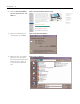
INSTALLATION 6 2. Click the Download ABPlot Software (Version 1.00 - 8.13 MB) link. Figure 1 Download AB-Plot Software Link 3. When the “File Download” window pops up, click Save. Figure 2 File Download Window 4. When the “Save As” window appears, choose the location that the download will be saved. Keep the location simple, as you will need to find the file later.
INSTALLATION 7 5. Once the file has saved to the specified location, find the file and double-click on it. This will start the installation. If any pop-up window appear asking if you would like to run the application or questioning security, click “OK” or “Yes.” Installation/Update procedure (from CD): Use the following instructions to install the application from CD. 1. Start Windows. 2. Insert CD in the disk drive. 3. Close all other applications and click on "My Computer". Activate the CD drive. 4.
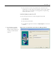
INSTALLATION 8 5. You are prompted to enter the drive or path to store the source files. After doing so, select Next. Figure 5 The “Choose Destination Location” Directory Dialogue Window 6. Finally, the Setup Program displays the message that the installation has been successfully completed. Should you have any questions or encounter any problems, please refer to Support and Updates for further advice.
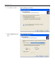
INSTALLATION 9 Installation/Update Procedure Using a Parallel Port: Use the following instructions if you intend to connect with a parallel port. For USB port instructions, please refer to USB Port Instructions on page 14. For Windows XP: 1. Click on Start, then select Settings, then Printers and Faxes. A similar window is visible: Figure 7 Selecting “Add a Printer” in Windows XP 2. This brings up the “Add Printer Wizard”: Select Next.
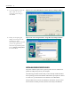
INSTALLATION 10 3. Select Local, then Next. Figure 9 Selecting a Local Printer 4. Select the parallel port for the plotter (typically LPT1) then Next.
INSTALLATION 5. Select Generic/Text Only driver, then Next.
INSTALLATION 12 6. Name the printer. It has been Figure 12 Naming the Printer named “Generic/Text Only” in this example. Select the printeras a default. Select Next. 7. Do not share the printer. Select Next.
INSTALLATION 8. Do not print a test page. Select Next. Figure 14 Not Printing a Test Page 9. Select Finish. Figure 15 Completing Add Printer Wizard Now the printer driver has been assigned to the parallel port.
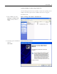
INSTALLATION 14 USB Port Instructions Use the following instructions if you will use a USB port to connect the printer. 1. Connect the printer to the computer via the USB port. A similar window will appear. 2. Select “No, not this time.” and click Next.
INSTALLATION 3. Select “Install from a list or specific location (Advanced).” Click Next. Figure 17 Found New hardware Wizard-Installing Software 4. A new pop-up will appear. Go to the location of the AB-Plot software and select the “USBDRV” folder. Click OK.
INSTALLATION 16 5. In the “Found New Hardware Window,” the wizard will automatically put in the location of your software as a search option. Click Next. Figure 19 Found New Hardware Wizard-Installation Process Options 6. Once the wizard has finished installing the driver, click Finish. Figure 20 Completing the Found New Hardware Wizard AN INTRODUCTION TO PLOTTER SOFTWARE These instructions guide you step by step to start PLOTTER SOFTWARE and calibrate the plotter.
INSTALLATION STARTING THE PLOTTER PROGRAM Start the program by opening the START menu, and navigating to: Programs/ABPLOT/AB-PLOT Note: The first time you open the software, you may be asked “Would you like to install the sub program for long file names support?” Select Yes. Installing this program allows the user to assign file names longer than 8 digits. Figure 21 Starting the AB-Plot Software CALIBRATING THE PLOTTER PLATE 1.
INSTALLATION 18 2. Select OK in order to call up the Input Screen. Figure 23 The Marker Card Format Window 3. Double click on the highlighted plate location to display the Input screen. Figure 24 The Plate Location Window with Marker Style Assigned 4. The screen now contains a representation of the Marker Card you have selected. The current marker, bottom left, is shown highlighted. Type an X on the 4 markers in the corners of the marker card.
INSTALLATION 5. Install a pen in the lower left penholder of the plotter. Install the appropriate marker card in the respective plate location. Hint: You can avoid wasting marker cards during this calibration by taping a clear transparency over the entire marker card. 6. Next, select the "File" menu, then "Plot..." or press the Figure 26 The Plot Window button on the toolbar ; the Plot window then appears (make sure that the Plotter is switched on and loaded with the appropriate Marker Card). 7.
INSTALLATION 20 Figure 28The Plotter Settings Window for Default Plotter (USB Connection) 8. Select the appropriate device type. 9. In order to calibrate the plotter, select the Adjust ref. point . . . button. This will bring up the Reference Point Adjustment window.
INSTALLATION 10. To move the plotter arm to the calibration cross at the upper left corner of the plotter plate fixture, do either of the following: a. Click on the arrow buttons on the computer screen. 21 Figure 29 The Plotter Plate Calibration Window b. Click on either of the numbered boxes, then press Enter on your keyboard. To make adjustments, either use the arrow buttons on the computer screen or type in a different number. TIP Use transparent tape to avoid marking the plate.
THE INPUT SCREEN 22 THE INPUT SCREEN Double-click on a marker card location in the Plate Location Window (see Figure 22), then select a Marker Card Type. This brings up the Input Screen. Figure 30 The Input Screen After Selecting a Marker Card Type The scroll buttons (located in the lower left corner of the screen) will bring the marker card from another plotter plate location (locations 1-5) to view. In particular, each scroll button will bring about another marker card as follows: 1 2 3 4 1.
THE INPUT SCREEN 23 Figure 31 Direction of Labelling There are three ways in which you can index to another marker in the marker card: 1. By means of the ENTER key, the user moves to the next marker within a row. At the end of a row, the user moves to the first marker in the next row. 2. By means of the cursor keys, the user moves one marker up, down, left or right each time. 3. By clicking with the mouse, every individual marker can be directly selected.
THE INPUT SCREEN 24 THE MENU BAR OF THE INPUT SCREEN File New Opens the Marker Card format window for choosing a new Marker Card. Open Opens an existing document. Save (Shortcut: Ctrl + S) Saves the current document under its file name. In the case of a document which has not yet been saved, the standard dialogue field "Save as..." appears automatically. Save as Loads the standard dialogue field "Save as..." for saving the current document with path details.
THE INPUT SCREEN 25 Edit Undo (Shortcut: Ctrl + Z) Reverses the last action Reverse data of marked rows (Shortcut: F9) First, highlight a row of markers (e.g. 1,2,3,4). Next, select this function.
THE INPUT SCREEN 26 Format Deletes the formatting information of the marked area Clear Marker Card (Shortcut: Shift + Del) Deletes the text and formatting information of the whole Marker Card.
THE INPUT SCREEN 27 Window Document No. # Allows selection of open documents. Options (available in Card Edit view only) Multiple lines Single line Help About Switches the highlighted area to the multiple line mode. Switches the Highlighted area to the single line mode.? (Shortcut: F1) Calls up the AB-Plot help routine.
THE INPUT SCREEN Input 28 The extent of the labelling is specified here. The given values refer to the marked area. Start value Any numerical value with which the labelling is to begin. End value Any numerical value with which the labelling is to finish Prefix One or more alphanumeric characters added before the number Suffix One or more alphanumeric characters added after the number Block Another numeral which allows a block-type allocation of the labelling text.
THE INPUT SCREEN 29 (This section provides the additional functions described below.) Options Step Determines the mode of counting, i.e. the increment between successive values. Example: step=1 ? 1 2 3 4; step=2 ? 1 3 5 7 Block step Determines the mode of counting for blocks. Duplicate each value Specifies how many copies of one marker are produced (with the same text) Duplicate sequence Specifies how many times a block is repeated.
THE INPUT SCREEN 30 Control Characters for Autofill Functions The following special characters may be used to execute user-defined numbering formats: 0 (zero) Results in a digit on the marker instead of a zero. If the resulting value at this position does not contain a digit, then AB-Plot produces a zero. If the start value is 1 and the end value 3, then entering 0#.00 in the formatting field results in 01.00 ? 02.00 ? 03.00 on the marker. # Results in a digit on the marker instead of "#".
THE INPUT SCREEN 31 Figure 33The Marker Card Configuration Window Close all marker cards before modifying the configurations. The Marker Card Configuration window is called up from the Program Screen via the "Edit Marker Card configurations..." command in the "Options" menu. This window is used for configuring existing or new Marker Card types and for a fast check of existing configurations. Information The list (bottom left) contains all the Marker Card types contained in the GRAPHAB.
THE INPUT SCREEN 32 Close The "Close" button exits the Marker Card Configuration window. Any values which have been altered are retained as long as the application remains in operation and are then saved. Cancel The "Cancel" button closes the Marker Card Configuration window and ignores any changes. Important The values of the first list entry cannot be stored. This type of Marker Card assumes that a Marker Card has already been selected.
THE INPUT SCREEN 33 The import of data from programs like Microsoft Excel is also possible via the simple copy function. To do this, the data is marked and copied in the other application (e.g. in Excel with Ctrl + C) and then pasted directly into AB-Plot from the clipboard. Various options can be selected here in order to recognize/generate project fields.
THE INPUT SCREEN 34 Figure 36 The CTRL + V Fill Algorithm Ctrl + Shift + V The first column of the table is taken as the project field and empty markers are filled. Figure 37 The CTRL + SHIFT + V Fill Algorithm EXPORTING DATA Figure 38 The Export Window The export function is started by selecting "Export..." from the "File" menu of the Input Screen. The export window then appears.
THE INPUT SCREEN 35 Text *.txt In this format, project fields and marker data are exported together. If the data to be exported is stored the program automatically opens another window with the designation "Export". Note: When exporting from one marker format to a different format the input text is not adjusted to the size of the marker.
PLOTTING 36 PLOTTING The plotting of markers and project information is carried out in the following steps: 1. A plot file with the values of the Plotter installed is created and saved to the hard drive. 2. The plot file (print job) is sent to an output device. Ensure the plotter plate has been calibrated prior to plotting. The Output Window Figure 40 Configuring the Output The Output window is called up from the Marker Card or Input Screen by selecting the command "Plot...
PLOTTING Highlighted marker Selected Marker Card 37 Only highlighted markers are plotted. Only selected Marker Cards are plotted. You can configure the parameters of the plotter/printer by actuating the "Settings..." button. Pressing "OK" starts the plot output; "Cancel" exits the Output window without starting the plot. PLOTTING PLOTTER CONNECTION The plotter is connected to the computer by means of a parallel or USB cable.
PLOTTING 38 Figure 41 Configuring the Default Plotter The settings to be used with this type of output can be defined by actuating the "Settings..." button after selecting the Plot option in the plot window. Alias The Alias field can be used to give the output device its own individual name. Device type Select the plotter type that is being used: •1492-PLTKIT Series C, D •1492-PLTKIT Series E Device driver The Generic/Text only printer driver.
PLOTTING 39 Figure 42 The Plot Preview Window INFORMATION THE RIGHT MOUSE BUTTON After highlighting a Marker Card area with the mouse (left button), pressing the right button opens a pop-up menu containing the most important functions (Autofill, Cut, Copy, Paste, Multiple paste, Insert copied markers, Delete, Insert cells, Delete cells, Import, Plot) used in the Input Screen. Apart from the functions Import and Plot, all commands apply to the marked area.
PLOTTING 40 SUPPORT AND UPDATES Information service You can access information about software and product updates by visiting our website at: http://www.ab.com/industrialcontrols/products Our website contains information about products and allows you to download updates and other information. Telephone hotline for users If you have any questions regarding our products, then please contact: Tel: 440-646-5800 E-mail: raictechsupport@ra.rockwell.
PLOTTING Function Shortcut, Function Key Availability Plot Ctrl + P Marker Card Screen, Input Screen Cut Ctrl + X Input Screen Copy Ctrl + C Input Screen Paste Ctrl + V Input Screen Select all Ctrl + A Marker Card Screen Mark all Ctrl + A Input Screen Clear marker card Shift + Del Input Screen Autofill functions F8 Input Screen Multiple lines Ctrl + ENTER Input Screen Help F1 During the whole application 41 DEFINITIONS Block More than one highlighted marker.
Pop-up menu A menu which appears within the application window by actuating the right mouse button. Project field This is the outside rim (sprue) of a Marker Card which the individual markers are attached to. Additional information may be written here which helps to allocate the markers in the field afterwards. Note that some markers (1492-MR5X12, MR6X12, MR8X12, etc.) cannot have their project fields plotted upon.
PLOTTING 43 GRAPHAB.GDM directly in the AB-Plot installation directory. Warning! Always make a back-up copy of the GRAPHAB.GDM file first before making any changes. Even the most insignificant of modifications can render all existing configurations useless. All dimensions in the file must be divisible by 25.
PLOTTING 44 Dim. Description Fig. 9800 Length of marker (µm) dim. 7 249000 Total length of Marker Card (µm) dim. 8 12 No. of rows per Marker Card 16744192 Decimal value of a color. This is identical with the color of the underlay which is to be used when plotting. This decimal value is calculated from the color proportions of the primary colours (red/green/blue). 163 500 Article code for marker type 500 Y-offset from reference point. Height difference to set reference point.
PLOTTING [PATH] 45 Path details of files required GRAPHGDM=C:\ABPRINT\GRAPHAB.GDM Path of Marker Card configuration file SAVEDIR=C:\ABPRINT\DATA\ Standard directory for Save as... OPENDIR=C:\ABPRINT\DATA\ Standard directory for Open... IMPORTDIR=C:\ABPRINT\DATA\ Standard directory for Import... EXPORTDIR=C:\ABPRINT\DATA\ Standard directory for Export... It is possible to modify the pre set separating character for file import from text files under the Terminator heading.
Publication 1492-UM007A-EN-P - October 2006 Copyright ©2006 Rockwell Automation, Inc. All Rights Reserved. Printed in USA.