AADvance The Next Step in Automation AADvance Controller System Build Manual Issue: 08 DOCUMENT: 553632 (ICSTTICSTT-RM448_EN_P) RM448_EN_P)
System Build Manual (AADvance Controller) This page intentionally left blank ii Document: 553632 (ICSTT-RM448_EN_P) Issue: 08:
Notice In no event will Rockwell Automation be responsible or liable for indirect or consequential damages resulting from the use or application of this equipment. The examples given in this manual are inluded solely for illustrative purposes. Because of the many variables and requirements associated with any particular installation, Rockwell Automation does not assume responsibility or reliability for actual use based on the examples and diagrams.
System Build Manual (AADvance Controller) Issue Record Issue Date Comments 01 April 2008 First Issue 02 Feb 2009 Update for Product Titles 03 Nov 2009 Update for Release 1.1 04 July 2010 Update for Release 1.1.1 05 Oct 2010 Updates for UL Certification 06 March 2011 Updated for Release 1.2 07 Aug 2011 Updated for UL Requirements 08 July 2012 Updates for release 1.3 and 1.3.
Notes and Symbols used in this manual This symbol calls attention to items which "must" be considered and implemented when designing and building an AADvance controller for use in a Safety Instrumented Function (SIF). It appears extensively in the AADvance Safety Manual. Note: Notes are used extensively to provide important information about the product.
System Build Manual (AADvance Controller) Foreword The AADvance controller is a logic solver consisting of one or more processors and a family of I/O modules. An AADvance system can be built from one or more AADvance controllers and/or standard controllers. This technical manual describes how to assemble a system, switch on and validate the operation of a controller. Scope of System Build Manual Who Should Use this Manual This manual is intended primarily for System Integrators.
System Build Manual (AADvance Controller) Contents Chapter 1 Product Overview ................................................................................... 1-1 The AADvance Controller .............................................................................................................................. 1-1 Controller TUV Certification ...................................................................................................................
Chapter 3 Install the AADvance System................................................................. 3-1 Unpacking and Pre-assembly Checks ............................................................................................................ 3-1 Install Base Units and termination Assemblies: Enclosure DIN Rail Assembly Method ................... 3-2 Allocations of Coding Pegs ........................................................................................................................
System Build Manual (AADvance Controller) Upgrade the Processor Module Recovery Mode Firmware ............................................................ 4-14 Stage 2: Installing the ControlFLASH Firmware Kit for OS, FPGA, LSP and BUSP .................. 4-19 Upgrade Processor OS, FPGAFPGA, LSP and BUSP Firmware ..................................................... 4-20 Setting Up the Controller IP Address for AADvance Workbench Communications .................... 4-24 Controller IP Address Setting.......
Chapter 1 Product Overview This chapter provides an overview of a controller and briefly describes its major components. In This Chapter The AADvance Controller ............................................................................... 1-1 Physical Features .................................................................................................
System Build Manual (AADvance Controller) All of the configurations are readily achieved by combining modules and assemblies without using special cables or interface units. System architectures are user configurable and can be changed without major system modifications. Processor and I/O redundancy is configurable so you can choose between fail safe and fault tolerant solutions.
The AADvance controller is developed and built for IEC 61131 compliance and includes support for all five programming languages. Program access is secured by a removable "Program Enable" key. Simulation software lets you prove a new application before reprogramming and downloading, again maximizing system uptime. Controller TUV Certification Certification TÜV Certification TÜV is the safety certifying authority for an AADvance controller.
System Build Manual (AADvance Controller) Certification for use in Hazardous Environments The AADvance controller has been investigated and approved by UL (UL508) for use as Industrial Control Equipment in a general industrial environment and for use in hazardous locations, Class I, Division 2, Groups A, B, C and D. The UL file numbers are: E341697 and E251761.
Document: 553632 (ICSTT-RM448_EN_P) Issue: 08: 1-5
System Build Manual (AADvance Controller) The AADvance controller has also been evaluated under certificate IECEx UL 12.0032X to the standards IEC 60079-0; (5th Edition) and IEC 60079-15 (4th Edition). [ certificate to be supplied] For a system that is located in a Zone 2 Hazardous environment where ATEX certification is required, all modules should be installed in an ATEX and IECEx Certified, tool accessible IP54 enclosure.
AADvanceDiscover Utility The AADvanceDiscover utility is installed when you install the AADvance Workbench, and appears on the Start menu of the computer. Click on AADvance Discover to start the AADvanceDiscover utility. The AADvanceDiscover utility displays a list of the AADvance controllers on the broadcast network, and reports a status for each one: Configurable Locked No response Double-clicking on an entry in the list lets you inspect the resource and IP address settings for a controller.
System Build Manual (AADvance Controller) Physical Features An innovative feature of the AADvance controller is the design of the hardware. Everything fits together easily without any need for inter-module wiring. Environmental Specification The following environmental specification defines the minimum recommended environmental conditions for an AADvance controller installation. Additional conditions apply to installations in a Hazardous environment.
Operating 0 to 2000m (0 to 6,600 ft.) Storage and Transport 0 to 3000m (0 to 10,000 ft.) This equipment must not be transported in unpressurized aircraft flown above 10,000 ft. Electromagnetic Interference Tested to the following standards: EN 613261:2006, Class A; EN 61326-3-1:2008, EN 54-4: 1997, A1; EN 61131-2:2007; EN 62061:2005.
System Build Manual (AADvance Controller) Summary of Dimensions Attribute Value Base unit dimensions (H × W × D), approx. 233 × 126 × 18mm (see text) (9-¼ in × 5 × ¾ in) Module dimensions (H × W × D), approx. 166 × 42 × 118mm (6-½ in × 1-⅝ in × 4-⅝ in) The depth of the base unit (18mm) excludes the parts of the backplane connectors that mate inside the module connectors.
Base units are moulded from a similar material. Each base unit can be mounted onto standard DIN rails or directly onto a panel or wall. The moldings incorporate slots and clamps for DIN rail mountings, and holes for screw fixing. Module Polarization Keying For each I/O Module there is a matched termination assembly set. The controller incorporates module polarization keying to ensure they are matched when installed.
System Build Manual (AADvance Controller) Module Locking Mechanism Each module carries a locking mechanism, which secures the module onto its base unit. The locking mechanism is in the form of a clamp screw, visible on the front panel of the module and engaged by a quarter turn of a flat blade screwdriver. The module senses the locking mechanism position and notifies the controller accordingly.
Part No: Digital Input Fuses T9901: No 396/TE5 50mA time lag fuse; UL 248-14, 125 V,T Leadfree; manufactured by Littlefuse. Part No: Digital Output Fuses T9902: SMF Omni-Block, Surface Mount Fuse Block 154 010, with a 10A, 125V Fast Acting Fuse, Littlefuse. WARNING FUSE REMOVAL or REPLACEMENT When the controller is installed in a Hazardous environment do not remove or replace a fuse when energized. Field Wiring Connections Field connections are made using industry-standard screw terminal blocks.
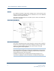
System Build Manual (AADvance Controller) T9100 Processor Base Unit Every AADvance controller has one T9100 processor base unit. A processor base unit supports one, two or three modules depending on the architecture chosen for the application.
The processor base unit provides the electrical connections between the T9110 processor modules, and the rest of the controller modules and has the following connections: Command and response bus connections for up to 48 I/O modules Inter-processor links Two Ethernet 100 BaseT connectors per processor Two serial data connections per processor Dual +24v System power Ground stud Program enable key The processor base unit holds the IP address of each processor module separately in a BUSP (U1 show
System Build Manual (AADvance Controller) Serial Communications The serial ports (S1-1 & S1-2, S2-1 & S2-2, S3-1 & S3-2) support the following signal modes depending upon use: RS485fd: A four-wire full duplex connection that features separate busses for transmit and receive. This selection should also be used when the controller is acting as a Modbus master using the optional four-wire definition described in Section 3.3.3 of the Modbus-over-serial standard.
The bus and power connections from the processor base unit enter the backplane at the left connector and are routed direct to the module connectors. The backplane provides a connector at the right for the next I/O backplane. The connection to the left of the backplane can connect to a processor base unit or another I/O base unit. Adjacent base units clip together and are held in position by a plastic retaining clip.
System Build Manual (AADvance Controller) T9310 Expansion Cable Assembly The T9310 expansion cable assembly connects a T9300 I/O base unit to another I/O base unit or to the T9100 processor base unit. The assembly consists of a cable, terminated by multi-way plugs, and a pair of adaptors. One end has a cable socket assembly and the other end a cable plug assembly that connects to the right-hand bus connector of an I/O base unit or to IO Bus2 (the left hand connector) of a processor base unit.
Backplane Electrical Ratings The following are the voltage and current ratings for the Process and I/O backplanes: Module Back-plane Electrical Ratings Input/Output Electrical Ratings Voltage (Vdc) Current (mA) 9100 18-32 10.4A (400mA per slot) - 9101 18-32 10.4A (400mA per slot) - 9300 18-32 9.6A (400mA per slot) - 9110 18-32 380 - 9111 18-32 380 - 9401 18-32 260 Input: 18-32Vdc @ 24mA 9402 18-32 260 Input: 0-32Vdc @ 6.5mA 9431 18-32 260 Input: 0-32Vdc @ 6.
System Build Manual (AADvance Controller) This page intentionally left blank 1-20 Document: 553632 (ICSTT-RM448_EN_P) Issue: 08:
Chapter 2 Before You Begin This chapter lists important information the reader should consider before starting to build the system. It includes preparatory information necessary for a successful installation. In This Chapter Required Tools Standard AADvance ............................................................. 2-1 Test Equipment ................................................................................................... 2-2 System Installation Environment ....................................
System Build Manual (AADvance Controller) Test Equipment The assembly of the system does not require the use of test-equipment, however, the preparation for initial switch on and start up may require the use of a multimeter. An engineering workstation running the Workbench programming software will be needed for communicating with the system, downloading the application software and for monitoring system variables and application logic.
Recommended Enclosure for a nonnon-hazardous environment An AADvance system must be installed in a suitable enclosure to maintain a Pollution Degree 2 (IEC 60664-1) environment. When used in an ATEX Zone 2 atmosphere the enclosure must provide a minimum ingress rating of IP54.
System Build Manual (AADvance Controller) Free Space Around the Controller The controller requires a free space at least 140mm deep (from front to back) between the rear panel of an enclosure and the inside of an enclosure door. If you wish to mount the controller on DIN rails, increase this allowance by the additional depth of the DIN rails. You must allow sufficient free space around the base units.
DIN Rails Rails Fitting You can install the AADvance controller onto a pair of parallel DIN rails. The DIN rails must be TS35 rail, which is 35mm × 7.5mm standard symmetric rail. Alternatively, you can install the controller onto a flat panel. The fixing dimensions are given below for both methods. A typical DIN rail arrangement is shown below: An application using DIN rails must provide the DIN rail free space to the left to fit an end stop on the upper DIN rail.
System Build Manual (AADvance Controller) Base Units, DIN Rail installations and Expansion Cables Cables Base units fit together side by side. One I/O base unit can be fitted directly onto the right hand edge of the processor base unit. The second and subsequent base units connect directly to the right of this first I/O base unit If required, termination assemblies can bridge adjacent I/O base units to save space.
Adding Cable Management The field, power and other system wiring will be connected to terminals along the top of the base units. It is recommended a length of trunking or similar be located above each set of base units, for cable management. Controller Design Considerations for Heat and Cooling The controller is designed to operate in its specified environment without forced air cooling.
System Build Manual (AADvance Controller) PELV (protected extra-low voltage) is an extra low voltage circuit with a protective partition from other circuits which has a protective earth connection. Thus to meet SELV and PELV requirements the power source must have a safety transformer with a protective partition between the primary and secondary windings so that the windings are galvanically and electrically isolated.
Power Arrangements for Field Devices The input circuits and the output modules of the controller require an external source of power for field devices. This may be the power source used for the controller or a separate power source, depending on the application. For digital and analogue outputs a field power supply of + 24V dc within a range of 18 - 32V dc is required. The power distribution circuit for each field input and for each output module must be protected, externally to the controller.
System Build Manual (AADvance Controller) Total: Note: All figures given are worst-case estimates based upon maximum operating field current and voltages. Estimate AADvance Controller Weight Use the following table to estimate the weight of your system. Table 4: AADvance Controller Module Weight Item Number Used Weight Allowance g (oz.) T9100 Processor Base Unit × 460g (16 oz.
Design Considerations for Electrical Grounding All applications of the controller will require at least two separate ground (earth) systems: An AC safety ground (sometimes called the 'dirty ground') to protect people in the event of a fault. The ground stud on the T9100 processor base unit, and all exposed metalwork such as DIN rails, will be bonded to the AC safety ground.
System Build Manual (AADvance Controller) Specifying the Workstation PC The workstation PC which runs the Workbench and other software requires the following specification: Operating system: Windows XP with Service Pack 3 Windows Vista, Windows 7 & Server 2003 in both 32-bit and 64-bit versions Note: Windows 64-bit versions will not recognize Workbench software licenses.
Design Provisions The design of the controller installation should make the following provisions: Clear access to remove and install modules, termination assemblies, base units and security dongle (Program Enable key). Repair of controller modules will be by module replacement. A way for plant operations personnel to inspect the status LEDs on each module. The status LEDs report faults. Clear access to examine, remove and install fuses located on the termination assemblies.
System Build Manual (AADvance Controller) In addition, it may be appropriate to make the following provisions: A lock on the door of the enclosure, to deter unauthorized access and possible unofficial modifications. Lighting. Utility sockets.
Chapter 3 Install the AADvance System The system installation defines the steps that will ensure the system is correctly installed and ready for the on-site factory tests before the system is brought on-line. This chapter describes how to install the AADvance system hardware into the chosen enclosure. In This Chapter Unpacking and Pre-assembly Checks ............................................................. 3-1 Install Base Units and termination Assemblies: Enclosure DIN Rail Assembly Method ..........
System Build Manual (AADvance Controller) CAUTION Handling Modules Stored at Extreme Temperatures It is recommended that modules removed from storage should be allowed to normalize their temperature before installation. This is particularly important when modules have been stored at very low temperatures where condensation can occur. Remove the modules and place them in an upright position and wipe away any condensation that might appear on the modules.
Insert the retaining clip on the back of the termination assembly into the slot on the I/O base unit. Press the termination assembly onto the base unit and then slide the assembly upwards as far as it will go. Make sure the retaining tab clips over the printed circuit board to secure the termination assembly in position. 7) Check coding pegs. Observe the legend on the 9100 processor base unit (and repeated on some termination assemblies) which defines the six possible positions for a coding peg.
System Build Manual (AADvance Controller) Allocations of Coding Pegs Coding pegs are assigned to each module type as shown in the following table: Application Key A Key B Key C 9100 processor base unit (for 9110 processor module) 1 1 1 9801/2/3 digital input termination assemblies (for digital input modules) 2 1 1 9831/2/3 analogue input termination assemblies (for analogue input modules) 2 1 3 9851/2 digital output termination assemblies (for digital output modules) 3 1 1 9842/1 analog
Use only finger pressure to manipulate and engage the clips. Do not attempt to use a screwdriver or other tool as injury or equipment damage may result. Use two clips for each join. 3) Mark off the panel to locate hole positions for three screws for each base unit. You can place the assembly of base units onto the panel and use the assembly as a template, or refer to the illustration to locate the holes. Mark and drill the panel and then secure the base units. M5 screws are suitable.
System Build Manual (AADvance Controller) Allocations of Coding Pegs Coding pegs are assigned to each module type as shown in the following table: Application Key A Key B Key C 9100 processor base unit (for 9110 processor module) 1 1 1 9801/2/3 digital input termination assemblies (for digital input modules) 2 1 1 9831/2/3 analogue input termination assemblies (for analogue input modules) 2 1 3 9851/2 digital output termination assemblies (for digital output modules) 3 1 1 9842/1 analog
Connect the AC Safety Ground Connection The T9100 processor base unit has a ground stud which must be connected to the AC safety ground. Connect the ground stud to the AC safety ground busbar of the system or panel. Use conductor wire of 10AWG (4mm2) with a temperature rating of 85ºC. Use a M6 lug on the end of the ground wire. Place the lug below the second nut on the ground stud, between two washers, and use two 10mm wrenches to tighten the nuts to a torque of 1.2Nm (0.74Ib/ft)n to 2Nm(1.48lb/ft).
System Build Manual (AADvance Controller) For each power supply connection, do the following: Connect the negative line from the power supply, typically labelled '0V', to the lefthand terminal. Connect the positive line from the power supply, typically labelled '+24V', to the right-hand terminal. Apply a minimum tightening torque of 0.5 Nm (0.37 ft lb) to the terminal screws. Note: Make sure that PWR-1 and PWR-2 are supplied from independent 24V dc sources. Refer to the illustration for an example.
Power and External Connector Wiring Details External connectors for power, serial data, Ethernet data and the application security device are connected to the T9100 Processor base unit. The field connections for I/O data are connected to the Termination Assemblies.
System Build Manual (AADvance Controller) Procedure Procedure to Connect Serial Communications Cabling Connect the serial communications cabling to the six plugs labelled S1-1 through S3-2 on the T9100 processor base unit. For each serial communications connection, connect the cabling according to the following illustration. Apply a minimum tightening torque of 0.22Nm (0.16ft lb) to the terminal screws. Make sure the length of the cable does not exceed 1,200m (3,900ft).
Note: Each processor uses the two serial ports above it on the baseplate. Data is not mirrored between ports. Therefore a single processor system has two ports available, a dual processor system has four ports and a triple processor system has six ports available to it. RS485 FullFull-Duplex This is a 4-wire point to point connection. The receive end should always be terminated a resistor and capacitor as shown in the diagram or similar termination. The recommended values are 120R + 100nf.
System Build Manual (AADvance Controller) RS485 HalfHalf-Duplex The Half -duplex connections should be terminated with the recommended values as shown: System Security Serial networks are closed and local and have limited protocol functionality, therefore, immune to any external attack except local deliberate sabotage.
Removable media, such as USB storage devices and CDs, should be virus checked before use within the system. The program enable key (shown below) should be removed from the processor base unit after application download (not applicable to a Euro Controller). This provides read only access to controllers during normal operation. Connecting Field Wiring Connect the field wiring to the screw terminal blocks on the termination assemblies. Note: Use conductor wire with a cross section of 16AWG .
System Build Manual (AADvance Controller) Digital Input Field Loop Circuits Recommended Field Loop Circuits This section contains recommended field loop circuits for line monitoring digital inputs used in Emergency Shutdown or Fire & Gas applications.
The suggested values for R1 and R2 are as follows: R1 = 15K Ω 1%, 1W (maximum power dissipated is 47mW at 26.4V) R2 = 3K9 Ω 1%, 1W (maximum power dissipated is 182mW at 26.
System Build Manual (AADvance Controller) Connections to 9802/9803 Isolated Digital Input TA — 16 Channel Dual/TMR Apply a minimum tightening torque of 0.5 Nm (0.37 ft lb) to the terminal screws. Connections to 9801 NonNon-isolated Digital Input TA — 16 Channel Simplex Apply a minimum tightening torque of 0.5 Nm (0.37 ft lb) to the terminal screws.
Analogue Input Field loop loop Circuits These circuits can be used for simplex, dual and triple configurations of analogue input modules. Fit a fuse (as shown) in each circuit to protect the field wiring.
System Build Manual (AADvance Controller) 4-Wire Analogue Input Connections to T9831 NonNon-isolated Analogue Input TA — 16 Channel Simplex Apply a minimum tightening torque of 0.5 Nm (0.37 ft lb) to the terminal screws.
Connections to T9832/T9833 Isolated Analogue Input TA — 16 Channel TMR Apply a minimum tightening torque of 0.5 Nm (0.37 ft lb) to the terminal screws.
System Build Manual (AADvance Controller) Recommended Field Circuit for Digital Digital Outputs This circuit is suitable for simplex and dual configurations of digital output modules. The two 10A fuses shown are included on the termination assembly within the controller. The field power 5A fuses comply with UL508 requirements see illustration below..
Connections to T9851/T9852 Digital Output TA — 8 Channel Simplex/Dual Apply a minimum tightening torque of 0.5 Nm (0.37 ft lb) to the terminal screws. Recommended Circuit for Analogue Outputs These circuits are suitable for simplex and dual configurations of analogue output modules. All channels are isolated from each other but may be bridged at the '+' terminal if fed by a common system mounted supply.
System Build Manual (AADvance Controller) The above circuit is appropriate for devices that are powered by the system. The channel will pass a requested current between 0mA and 24mA. The field device could also be connected between the 24V supply and the Loop Plus terminal. Note: that if the 24V supply is shared between channels or between modules, the field loops will not be isolated from each other.
Note: Apply a minimum tightening torque of 0.5 Nm (0.37 ft lb) to the terminal screws. Connecting the AADvance Controller to an Ethernet Network The T9100 processor base unit has six auto-sensing 10/100BASE-TX Ethernet ports which allow it to connect to a local area network through standard Rj45 Ethernet cable. These are two ports for each processor module.
System Build Manual (AADvance Controller) Install Install Modules The modules of the AADvance controller mount onto the base units. The processor module(s) mount onto the T9100 processor base unit, while the various I/O modules mount onto the T9300 I/O base unit and associated termination assemblies. The product range includes two sizes of blanking covers to conceal unused module positions.
3) The module locking screw requires a quarter turn clockwise to lock. Use a broad (9mm) flat blade screwdriver to lock the locking screw. Note: The locking screw acts as a power interlock device. Therefore, the locking screw must be in the locked position after the power is applied otherwise the module will not boot up. Upgrade a Processor Module Firmware To upgrade ethe firmware use the Recovery Mode and follow the procedures using the ControlFLASH utility.
System Build Manual (AADvance Controller) (Part No: T9905 Poly-carbonmonofluride Lithium Coin Battery, BR2032 (recommended type) , 20mm dia; Nominal voltage 3V; Nominal capacity (mAh) 190; Continuous standard load (mA) 0.03; Operating temperature -30°C to 80°C, supplied by Panasonic. The battery will last for approximately 10 years under normal operating conditions, or approximately six months if the module is not in use. 1) Use a small cross head screwdriver to release the battery cover. Remove the cover.
4) To control the time setting, wire variables to the RTC Control points: RTC Write RTC Read 5) Wire Variables to RTC Control: Hours Minutes Seconds 6) Set RTC Read to be always True (the time will not be written unless this point is also True). 7) Set RTC Control elements Hours, Minutes and Seconds to be always True. 8) Use an external trigger to change RTC Write from False to True at the time you have preset in step 3.
System Build Manual (AADvance Controller) Install Blanking Covers Install a blanking cover to each spare position on the base units. Place the blanking cover on the base unit and use a broad (9mm) flat blade screwdriver to turn the clamp screw 90° to the lock position. Fit EMC Static Protection Covers For EMC static protection you should fit the black plastic protection covers (supplied with the base units) over any exposed 48 pin DIN connectors on the T9300 I/O Base unit.
Install T9310 Expansion Cable 1) The expansion cable ferrites are snap on components. Fit the ferrites 50mm (1.97) from each end and secure with cable ties either side of the ferrites. Connect Expansion Cable between T9100 Base Unit and T9300 I/O Base unit (IO Bus2) 1) Connect the expansion cable to a T9100 processor base unit for an IO Bus 2 connection. Insert a cable socket assembly into the left hand connector of the T9100 processor base unit.
System Build Manual (AADvance Controller) Secure the socket assembly by inserting the two M3 socket cap screws. Tighten the screws with a 2.5mm Allen key. Install the cable to the socket assembly and tighten the retaining screws by hand. 2) Insert the free end of the expansion cable into a right hand socket of a T9300 I/O base unit. Insert a cable plug assembly into into the right hand socket of the processor or I/O base unit.
Tighten the screws with a 2.5mm Allen key. Install the cable to the plug assembly and tighten the retaining screws by hand. 2) Connect the free end of the expansion cable to the left hand plug of an I/O base unit using a cable socket assembly. Insert a cable socket assembly into the left hand connector of the T9300 processor base unit. Secure the socket assembly by inserting the two M3 socket cap screws. Tighten the screws with a 2.5mm Allen key.
System Build Manual (AADvance Controller) Fault Reporting Reference Information Each module has a set of front panel status indicators.
GREEN Module is online and providing data to/receiving data from application AMBER Module is inserted into a running system but not online.
System Build Manual (AADvance Controller) and indicates that the module has no hardware faults. When in the recovery Mode and no faults are present the LED is GREEN Note: 1. If Healthy is GREEN and all the other indicators are OFF then the module has failed to boot up 2. If Healthy is GREEN and the Ready and Run are RED then the module is said to be in its shutdown state ( See topic - Module Shutdown State and Possible Causes in the Troubleshooting Manual Chap 3).
Force Provides an indication that variables are being locked/forced by the application. The same indication will show for all educated and synchronised processors OFF No power and stays off while the module is booting up (10 to 20 seconds) GREEN No variables are being locked/forced AMBER Module is in the Recovery Mode. or an operating controller has at least one variable being locked/forced Aux This LED is controlled by the application.
System Build Manual (AADvance Controller) This page intentionally left blank 3-36 Document: 553632 (ICSTT-RM448_EN_P) Issue: 08:
Chapter 4 System StartStart-Up This chapter describes a structured approach to the start up of a controller system. When the checks and module installation and start up is completed successfully, the system is ready for a Functional Acceptance Test. In This Chapter Recommendations to Manage Test Documentation.................................. 4-1 System Physical Design Check......................................................................... 4-2 Procedure to Verify Build State ........................
System Build Manual (AADvance Controller) System Physical Design Check Assess the physical design of the system to determine whether it is ready to be tested. Do the following: Verify there is physical segregation of any mains supply circuits from the 24V dc controller circuits. Review the arrangements of terminals and the provision of cable entries for field wiring. Evaluate the ease of access for maintenance activities.
Procedure to check Power Distribution Integrity Note: Before you begin this task, you must have checked the ground bonding. Check the integrity of the power distribution system to verify that each power distribution sub-section is wired in accordance with the drawings and that the subsections are isolated from each other. Do the following: 1) Make sure all power sources are isolated. 2) Switch off all circuit breakers and open distribution fuses. 3) Remove all modules from the controller.
System Build Manual (AADvance Controller) Start Up Process Once the procedures for power distribution tests have been successfully completed, the controller is ready for installation of its modules and its second power up. The installation process should be completed in the following order: 1) Switch off power to the controller — both field power and controller power sources. 2) Make a record of the module and base unit serial numbers for future reference. 3) Reinstate the power.
Step Task Force Will remain OFF as the Module boots up (10 to 20 seconds) then stays OFF until the module has educated. Aux Will remain OFF as the Module boots up (10 to 20 seconds) then is dependent upon data connection.
System Build Manual (AADvance Controller) Table 9: Procedure for Installation of a 2nd and 3rd Processor Note: The second and third processor modules must be programmed with the same firmware as the first processor. Check the firmware revision on the labels and if required use the procedure in the Configuration Guide. If the firmware revision is different to the first processor module you can download the latest firmware build to all the processor modules using the ControlFLASH utility.
Step Task When the Run indicator goes AMBER press the Fault Reset button and the processor will display the following indications: 2. 3.
System Build Manual (AADvance Controller) Ready GREEN Run AMBER Channel 1 – 8 Off 6. Press the Fault Reset button on the processor module and the Run indication goes GREEN. 7. The module will now be on-line with the following status indications: 8. Healthy GREEN Ready GREEN Run GREEN Channel 1 – 8) Dependent on channel status If the module fails to educate and go on-line replace the module. Table 11: Second or third Module of a Group Installation Procedure Step Task 1.
8. If the module fails to educate and go on-line replace the module.
System Build Manual (AADvance Controller) ControlFLASH Firmware Upgrades The AADvance controller supports upgrades of processor module firmware by using the ControlFLASH utility (I/O module upgrades using ControlFLASH are not currently supported in this release.) WARNING FIRMWARE UPGRADE DANGER TO A RUNNING SYSTEM Do not attempt to upgrade firmware on a running system. Control FLASH will not warn you that a system is running and you will lose control of the application when the system reboots.
The RSLinx Classic Lite software must be installed before you can install the ControlFLASH software. RSLinx software is a communications software package that you can use with a wide variety of rockwell automation applications and hardware. The ControlFLASH software uses the RSLinx Classic Lite software to communicate over Data highway Plus, DFI, DH485, ControlNet, DeviceNet and Ethernet networks.
System Build Manual (AADvance Controller) 3) Read and agree to the license and click Next 4) Click Browse to select the location of the installation or Next to select the default location. 5) Click Next to start the installation.
ControlFLASH installs. 6) To launch ControlFLASH select the Yes I want to launch controlFLASH option, then click Close.
System Build Manual (AADvance Controller) ControlFLASH will launch and you can now upgrade the Processor Module firmware. Upgrade the Processor Module Recovery Mode Mode Firmware This is the recommended procedure to upgrade the processor module firmware using the ControlFLASH Utility. Note: ControlFLASH can upgrade 3 processor modules at once when installed into a 9100 base unit and they are in the Recovery Mode.
2) Click Next. 3) Select T9110 from the list.
System Build Manual (AADvance Controller) 5) Select the firmware revision for the latest Release.
The continue message is displayed: 7) Click Yes to continue with the update A progress bar is displayed When the progress bar reaches the end, it may take several minutes for the next screen to appear.
System Build Manual (AADvance Controller) Note: It has not locked up! Wait until the next message box appears ! You may get a "Comms error message" as AADvance processors do not automatically reboot as ControlFLASH expects them to but the firmware download should have completed correctly. 8) Click OK. Wait another couple of minutes and the same message will appear again. 9) Click OK. 4-18 The following message now appears.
10) Click OK and another error message is displayed. 11) Click OK then Cancel to Exit ControlFLASH. 12) Reboot the processor module by switching the power OFF then ON and hold in the Fault Reset button as the module reboots until the Aux LED goes amber. The processor module(s) will reboot into the Recovery Mode indicated by the following LED states on the processor module.
System Build Manual (AADvance Controller) Upgrade Processor OS, FPGAFPGA, LSP and BUSP Firmware This procedure describes how to upgrade the processor module firmware using ControlFLASH. Note: ControlFLASH can upgrade 3 processor modules at once when installed into a 9100 base unit. WARNING FIRMWARE UPGRADE DANGER TO A RUNNING SYSTEM Do not attempt to upgrade firmware on a running system.
4) Browse to the device in the RSLinx window 5) Select the firmware revision for the latest Release.
System Build Manual (AADvance Controller) 6) Check the summary details, click Finish The continue message is displayed: 7) Click Yes to continue with the update 4-22 Document: 553632 (ICSTT-RM448_EN_P) Issue: 08:
A progress bar is displayed Note: if the processor is not in the Recovery Mode the following error is displayed. Follow the procedure in Stage 1 to download the recovery Mode. After the progress bar reaches the end, it may take several minutes for the next screen to appear. Use the View Module Firmware Versions procedure to verify that the upgrade has worked.
System Build Manual (AADvance Controller) Setting Up the Controller IP Address for AADvance Workbench Communications The AADvance controller stores a resource number and IP address information. These details have to match those defined in the AADvance Workbench for the application. After you have configured these details the AADvance Workbench can communicate with the controller. You use the AADvanceDiscover utility to set up the controller for AADvance Workbench communications.
Double-clicking on an entry in the list lets you inspect the resource and IP address settings for a controller. There is also a Refresh button, which makes a scan of the network and creates a new list. A controller is configurable when the program enable key is present (this plugs into the KEY connector on the processor base unit) and either no application is loaded or an application is loaded but not running.
System Build Manual (AADvance Controller) 3) Do not use an office network. Use an isolated hub or switch between the computer and AADvance controller. Check that the hub/switch has LEDs lit for the ports to both computer and controller, showing that the ports are working. 4) Open the Network Connections window. Open the Properties of the computer’s network adapter (as used for configuring AADvance).
The resource and IP Address dialog box opens. 6) Enter the resource value into the Resource Number field, click Apply. Returning to the main window of the utility, the controller status will show Pending Restart. 7) To complete the update, cycle the power to the controller. 8) Refresh the screen to confirm that the new resource number is displayed in the resource field and the controller status is configurable.
System Build Manual (AADvance Controller) 2) Make sure the program enable key is inserted in the KEY connector on the processor base unit. 3) Start the AADvanceDiscover tool from the Start menu: Start → All Programs → AADvance → AADvance Discover. The AADvanceDiscover utility scans the network for controllers, and creates a list. 4) Locate the controller in the list and make sure that the status of the controller is Configurable. 5) Double-click on the MAC address in the Controller ID field.
Returning to the main window of the utility, the controller status will show In Progress and then Configurable. The controller uses the new settings.
System Build Manual (AADvance Controller) This page intentionally left blank 4-30 Document: 553632 (ICSTT-RM448_EN_P) Issue: 08:
Chapter 5 Functional Acceptance Testing Functional acceptance testing, also known as factory acceptance testing or integration testing, will test the controller and its associated application software to make sure it satisfies the requirements defined in the requirements specification for an integrated system. When its applied to a safety related application then the safety requirements are also tested. In This Chapter Recommendations for Functional Acceptance ............................................
System Build Manual (AADvance Controller) Controller Configuration Testing should take place on a defined version of the controller. Record the type, serial number and physical location of module for shipping and later re-installation in their original locations.
Chapter 6 Dismantling the AADvance System In This Chapter About Dismantling a System ............................................................................ 6-1 About Dismantling a System Dismantling Dismantling is a reverse of the system assembly process. Disposal It will be necessary to arrange for the collection, treatment, recovery and environmentally sound disposal of the equipment at the end of its life. Contact Rockwell Automation to discuss the most appropriate way to do this.
Chapter 7 Parts List Bases Part No. Part Description T9100 Processor base unit T9300 I/O base unit (3 way) Modules Part No.
System Build Manual (AADvance Controller) T9831 Analogue input TA, 16 channel, simplex, commoned T9832 Analogue input TA, 16 channel, dual T9833 Analogue input TA, 16 channel, TMR T9851 Digital output TA, 24Vdc, 8 channel, simplex, commoned T9852 Digital output TA, 24Vdc, 8 channel, dual T9881 Analogue output TA, 8 channel, simplex commoned T9882 Analogue output TA, 8 channel, dual T9844 Frequency Input Module TA, Simplex, Active (not yet released) T9845 Frequency Input Module TA, Dual, Ac
T9903 Replacement coding pegs (pack of 20) T9904 Replacement backplane clips (pack of 20) T9905 Replacement processor 3V lithium cell (pack of 20) *see notes T9906 Replacement program enable key T9907 Installation tool kit T9908 Fuse Extractor Tool Software Part No. Part Description T9082U IEC 61131 Workbench, USB key, single user, single controller T9082D IEC 61131 Workbench, hard disk key, single user, single controller Part No.
System Build Manual (AADvance Controller) T9902: SMF Omni-Block, Surface Mount Fuse Block 154 010, with a 10A, 125V Fast Acting Fuse, Littlefuse. T9905: Poly-carbonmonofluride Lithium Coin Battery, BR3032, 20mm dia; Nominal voltage 3V; Nominal capacity (mAh) 190; Continuous standard load (mA) 0.
Glossary of Terms Glossary of Terms A asynchronous accuracy A data communications term describing a serial transmission protocol. A start signal is sent before each byte or character and a stop signal is sent after each byte or character. An example is ASCII over RS232-C. See also 'RS-232-C, RS-422, RS-485'. The degree of conformity of a measure to a standard or a true value. See also 'resolution'. achievable safe state A safe state that is achievable. Note: Sometimes, a safe state cannot be achieved.
System Build Manual (AADvance Controller) blanking cover C A plastic moulding to hide an unused slot in an AADvance base unit. CIP boolean A type of variable that can accept only the values 'true' and 'false'. BPCS Basic process control system. A system which responds to input signals and generates output signals causing a process and associated equipment to operate in a desired manner, but which does not perform any safety instrumented functions with a claimed safety integrity level of 1 or higher.
Chapter 7 Glossary of Terms consumer dictionary The consuming controller requests the tag from the producing controller. The set of internal input and output variables and defined words used in a program. contact A graphical component of a Ladder Diagram program, which represents the status of an input variable. discrepancy A condition that exists if one or more of the elements disagree. continuous mode DITA See high demand mode. Digital input termination assembly.
System Build Manual (AADvance Controller) fault reset button function block diagram The momentary action push switch located on the front panel of the 9110 processor module. An IEC 61131 language that describes a function between input variables and output variables. Input and output variables are connected to blocks by connection lines. See 'limited variability language'.
Chapter 7 Glossary of Terms hot swap instruction list See live insertion. An IEC 61131 language, similar to the simple textual language of PLCs. See 'limited variability language'. I I/O base unit A backplane assembly which holds up to three I/O modules and their associated termination assembly or assemblies in an AADvance controller. Part number 9300. See 'I/O module' and 'termination assembly'.
System Build Manual (AADvance Controller) M OPC manual call point A series of standards specifications which support open connectivity in industrial automation. A component of a fire detection and fire alarm system which is used for the manual initiation of an alarm. Modbus An industry standard communications protocol developed by Modicon. Used to communicate with external devices such as distributed control systems or operator interfaces.
Chapter 7 Glossary of Terms processor module RSRS-232232-C, RSRS-422, RSRS-485 The application execution engine of the AADvance controller, housed in a selfcontained and standardized physical form factor. Standard interfaces introduced by the Electronic Industries Alliance covering the electrical connection between data communication equipment. RS-232-C is the most commonly used interface; RS-422 and RS-485 allow for higher transmission rates over increased distances.
System Build Manual (AADvance Controller) SFF synchronous Safe Failure Fraction. Given by (the sum of the rate of safe failures plus the rate of detected dangerous failures) divided by (the sum of the rate of safe failures plus the rate of detected and undetected dangerous failures). A data communications term describing a serial transmission protocol. A pre-arranged number of bits is expected to be sent across a line per second.
Chapter 7 Glossary of Terms U U Rack unit. A unit of measure used to describe the height of equipment intended for mounting in a standard rack. Equivalent to 44.45mm (1-¾ inches). V validation In quality assurance, confirmation that the product does what the user requires. verification In quality assurance, confirmation that the product conforms to the specifications.
Chapter 9 Additional Resources Resources For more information about the AADvance system refer to the associated Rockwell Automation technical manuals shown in this document map. Publication Purpose and Scope Safety Manual This technical manual defines how to safely apply AADvance controllers for a Safety Instrumented Function. It sets out standards (which are mandatory) and makes recommendations to ensure that installations meet their required safety integrity level.
System Build Manual (AADvance Controller) PFH avg and PFDavg Data This document contains the PFHavg and PFDavg Data for the AADvance Controller. It includes examples on how to calculate the final figures for different controller configurations. The data supports the recommendations in the AADvance Safety Manual Doc No: 553630. Regional Regional Offices Rockwell Automation Oil and Gas Resources are available in Regional Offices worldwide.