AADvance The Next Step in Automation AADvance Controller PFH avg and PFD avg Data Issue: 04 DOCUMENT: 553847 (ICSTTICSTT-RM449_EN_P)
PFH avg and PFD avg Data (AADvance Controller) This page intentionally left blank ii Document: 553847 (ICSTT-RM449_EN_P) Issue 04:
Notice In no event will Rockwell Automation be responsible or liable for indirect or consequential damages resulting from the use or application of this equipment. The examples given in this manual are included solely for illustrative purposes. Because of the many variables and requirements associated with any particular installation, Rockwell Automation does not assume responsibility or reliability for actual use based on the examples and diagrams.
PFH avg and PFD avg Data (AADvance Controller) Issue record Issue Date Comments 01 Sept 2009 First Issue 02 March 2011 Update for Release 1.2 03 May 2012 Updates and corrections from peer review and from TUV review, add distributed SIF example. 04 June 2012 Update for Release 1.
Forward This document contains the PFHavg and PFDavg Data for the AADvance Controller. It includes examples on how to calculate the final figures for different controller configurations. The data supports the recommendations in the AADvance Safety Manual Doc No: 553630.
PFH avg and PFD avg Data (AADvance Controller) Contents Chapter 1 Introduction ............................................................................................. 1-1 Failure Rates ........................................................................................................................................................ 1-1 PFD Data - 8 Hour MTTR ...............................................................................................................................
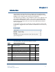
Chapter 1 Introduction The information in this document has been compiled as part of the AADvance IEC 61508 certification, the failure modes and Failure Mode Effect and Diagnostic Analysis (FMEDA) of each module having been inspected by TUV Rheinland. The tables below provide PFD avg data for AADvance modules used in applications with an 8 or 24 hour MTTR and with 6 months, 1 year, 5 years or 10 years Manual Test Interval (MTI).
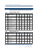
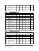
PFH avg and PFD avg Data (AADvance Controller) PFD Data - 8 Hour MTTR The following tables provide the probability of failures upon demand for the energize to action and de-energize to action Safety Instrumented Function (SIF) configurations. The Manual Test Interval is as indicated Table 2: Module PFD Data for a SIF with MTI = 6 months Module Description PFDde PFDe Single Dual Triple Single Dual Triple T9110 Processor module 6.16E-5 2.43E-7 2.58E-7 7.88E-5 4.07E-7 4.
T9451 Digital output module, 24Vdc, 8 channel, isolated, commoned 1.36E-6 2.73E-6 4.07E-5 4.09E-7 T9481 Analogue output module, 3 channel, isolated 3.98E-6 7.83E-6 1.52E-4 3.54E-6 T9482 Analogue output module, 3 channel, isolated 3.98E-6 7.83E-6 1.52E-4 3.54E-6 Table 4: Module PFD Data for SIF with MTI = 5 Years Module Description PFDde PFDe Single Dual Triple Single Dual Triple T9110 Processor module 5.91E-4 2.18E-6 3.55E-6 7.52E-4 3.72E-6 5.
PFH avg and PFD avg Data (AADvance Controller) T9451 Digital output module, 24Vdc, 8 channel, isolated, commoned 1.22E-5 2.43E-5 3.81E-4 4.00E-6 T9481 Analogue output module, 3 channel, isolated 3.93E-5 7.75E-5 1.48E-3 3.49E-5 T9482 Analogue output module, 8 channel, isolated 3.93E-5 7.75E-5 1.48E-3 3.
T9401 Digital input module, 24Vdc, 8 channel, isolated 5.12E-6 4.36E-7 4.36E-7 8.35E-6 4.60E-7 4.60E-7 T9402 Digital input module, 24Vdc, 16 channel, isolated 5.12E-6 4.36E-7 4.36E-7 8.35E-6 4.60E-7 4.60E-7 T9431 Analogue input module, 8 channel, 5.12E-6 isolated 4.36E-7 4.36E-7 8.35E-6 4.60E-7 4.60E-7 T9432 Analogue input module, 16 channel, isolated 5.12E-6 4.36E-7 4.36E-7 8.35E-6 4.60E-7 4.60E-7 T9451 Digital output module, 24Vdc, 8 channel, isolated, commoned 1.70E-6 3.
PFH avg and PFD avg Data (AADvance Controller) T9401 Digital input module, 24Vdc, 8 channel, isolated 3.46E-5 4.25E-6 4.25E-6 5.21E-5 4.42E-6 4.43E-6 T9402 Digital input module, 24Vdc, 16 channel, isolated 3.46E-5 4.25E-6 4.25E-6 5.21E-5 4.42E-6 4.43E-6 T9431 Analogue input module, 8 channel, 3.46E-5 isolated 4.25E-6 4.25E-6 5.21E-5 4.42E-6 4.43E-6 T9432 Analogue input module, 16 channel, isolated 3.46E-5 4.25E-6 4.25E-6 5.21E-5 4.42E-6 4.
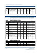
T9110 Processor module 2.69E-8 T9401 Digital input module, 24Vdc, 8 channel, isolated T9402 Digital input module, 24Vdc, 16 channel, isolated 3.41E-8 5.07E-9 5.52E-9 7.48E-10 4.77E-10 4.78E-10 1.11E-9 8.22E-10 8.27E-10 7.48E-10 4.77E-10 4.78E-10 1.11E-9 8.22E-10 8.27E-10 T9431 Analogue input module, 8 channel, 7.48E-10 4.77E-10 4.78E-10 isolated 1.11E-9 8.22E-10 8.27E-10 T9432 Analogue input module, 16 channel, isolated 7.48E-10 4.77E-10 4.78E-10 1.11E-9 8.22E-10 8.
PFH avg and PFD avg Data (AADvance Controller) Binding and PeerPeer-toto-Peer Communication Data (per segment) The PFH and PFD values for the Binding and Peer-to-Peer communications per segment are as follows: PFH = 1E-11 PFD = 1E-7 Safe Failure Fraction (SFF) and Hardware Hardware Fault Tolerance (HFT) The following table provides the SFF and HFT data for SIF configurations energize to action and de-energize to action mode.
System Configurations The PFH and PFD calculations are derived from IEC 61508 Section 6 and the examples below show how the calculations are used to define the probability of failure for a SIF. Example 1 This illustrates a SIL3 SIF with one signal input and one signal output; it has a MTI of 1 year and a MTTR of 8 hours, it is configured as a de-energized to trip arrangement.
PFH avg and PFD avg Data (AADvance Controller) Example 3 SIL3 SIF with 2 inputs on dual input modules and 1 output with a manual test interval of 1 year and MTTR = 8 hours as 1oo2 de-energize to trip. Refer to Table 3 Example 4 This illustrates a SIL 3 with 1 dual input and 2 outputs, with a manual test interval of 1 year and MTTR = 8 hours, configured as 1oo2 de-energize to trip.
Example 5 This illustrates a SIL 3 SIF distributed between two controllers, with one signal input and one signal output; it has a MTI of 1 year and a MTTR of 8 hours, it is configured as a de-energize to trip arrangement.