AADvance Controller Demo Unit User Manual ISSUE 1.
Demo Unit User Manual (AADvance Controller) Notice The content of this document is confidential to Rockwell Automation companies and their partners. It may not be given away, lent, resold, hired out or made available to a third party for any purpose without the written consent of Rockwell Automation. This document contains proprietary information that is protected by copyright. All rights are reserved.
Demo Unit User Manual (AADvance Controller) Contents Chapter 1 Introduction - Demo Unit....................................................................... 1-1 Demo Unit........................................................................................................................................................... 1-1 Dimensions and Weight................................................................................................................................... 1-2 Dimensions..........
Modbus Slave Communication Parameters ......................................................................................... 4-11 About T9110 Processor Variables............................................................................................................... 4-12 Wire Processor Variables........................................................................................................................ 4-12 Unwire Processor Variables.......................................................
Demo Unit User Manual (AADvance Controller) This page intentionally left blank vi Document: 553850 Issue 1.
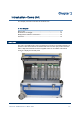
Chapter 1 Introduction - Demo Unit This chapter presents an overview of the demo unit. In This Chapter Demo Unit ........................................................................................................... 1-1 Dimensions and Weight.................................................................................... 1-2 Display Panel and Power Connectors ........................................................... 1-3 Overview ....................................................................
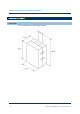
Demo Unit User Manual (AADvance Controller) Dimensions and Weight Dimensions The portable unit has the following dimensions: 1-2 Document: 553850 Issue 1.
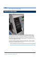
Weight The unit weighs approximately 18 Kgms. Display Panel and Power Connectors The display panel provides a visual indication from the analogue and digital output modules; it also has switches to drive digital inputs and potentiometers for analogue inputs signals.The four switches are connected to channels 1 to 4 of the 9401 digital input modul. The four analogue potentiometers are connected to channels 1 to 4 of the dual 9431 analogue input modules.
Demo Unit User Manual (AADvance Controller) Overview The Demo Unit is supplied with the following modules and termination assemblies: Part No: Title T9141 AADvance Demo Unit T9110 Processor Module T9110 Processor Module T9000 Processor Base Unit T9300 I/O Base unit (3-way) T9401 Digital Input Module, 24V dc, 8 channel T9801 Digital Input TA, 16 channel, simplex T9451 Digital Output Module, 24V dc, 8 channel T9451 Digital Output Module, 24V dc, 8 channel T9852 Digital Output TA, 16 chan
T9110 Processor Module The T9110 processor module is the central processing unit of an AADvance controller.
Demo Unit User Manual (AADvance Controller) Processor Module Specification Table 1: Processor Module Specification Attribute Value Functional Characteristics Degradation 1oo1D, 1oo2D and 2oo3D Processor clock 400MHz Memory Boot flash 512kB SRAM 512kB Bulk flash 64MB SDRAM 32MB Sequence of Events Event Resolution Application Scan Time-stamp Accuracy 5ms Performance Characteristics Safety Integrity Level (SIL) One module — non-safety applications, SIL1 and/or SIL2 safety applications Two
T9100 Processor Base Unit Every AADvance controller has one T9100 processor base unit. A processor base unit supports one, two or three modules depending on the architecture chosen for the application. Document: 553850 Issue 1.
Demo Unit User Manual (AADvance Controller) The processor base unit provides the electrical connections between the T9110 processor modules, and the rest of the controller modules and has the following connections: Command and response bus connections for up to 48 I/O modules Inter-processor links Two Ethernet 100 BaseT connectors per processor Two serial data connections per processor Dual +24v System power Ground stud Program enable key The processor base unit holds the IP address of eac
The bus and power connections from the processor base unit enter the backplane at the left connector and are routed direct to the module connectors. The backplane provides a connector at the right for the next I/O backplane. The connection to the left of the backplane can connect to a processor base unit or another I/O base unit. Adjacent base units clip together and are held in position by a plastic retaining clip.
Demo Unit User Manual (AADvance Controller) T9401/2 Digital Input Module, 24V dc, 8/16 channel The T9401/2 digital input module monitors eight (T9401) or sixteen (T9402) isolated digital input channels and notifies the processor module of each field device state and channel condition. Each channel provides both digital state and analogue voltage data to the processor module for field device state, line monitoring and field fault detection.
T9401/2 Digital Input Module Specification Table 2: T9401/2 Digital Input Module Specification Attribute Value Functional Characteristics Input Channels T9401: 8 T9402: 16 Degradation 1oo1D, 1oo2D,2oo3D Performance Characteristics Safety Integrity Level IEC 61508 SIL3 Safety Accuracy Limit 1% Sample Update interval (no filter) 5ms Self Test Interval Not Applicable Sequence of Events Event Resolution Time-stamp Accuracy 1ms 5ms Electrical Characteristics Supply Voltage Redundant + 24Vdc nom
Demo Unit User Manual (AADvance Controller) T9451 Digital Output Module, 24V dc, 8 channel The T9451 digital output module interfaces up to eight final elements and can switch 1A at 32V dc for each device. It features voltage and load current monitoring on each channel, reverse current protection and short and open circuit line monitoring. It is designed to always be able to switch off an output when demanded. No single failure within the module can cause a stuck-on failure.
T9451 Digital Output Module Specification Table 3: T9451 Digital Output Module Specification Attribute Value Functional Characteristics Number of output channels 8 per module Degradation 1oo1D, 1oo2D Performance Characteristics Safety integrity level IEC 61508 SIL3 Self-test interval <30 mins (30s per module) Electrical Characteristics Supply Voltage Redundant +24V dc nominal; 18V dc to 32V dc range Output characteristics: Operating field supply voltage 0V to +50V dc Maximum voltage without
Demo Unit User Manual (AADvance Controller) T9431/2 Analogue Input Module, 8/16 Channel The T9431/2 analogue input module monitors eight (T9431) or sixteen (T9432) isolated analogue input channels and notifies the processor module of the field device value and channel condition. Each channel provides digital state and analogue process value data to the processor for process monitoring, line monitoring and field fault detection.
T9431/2 Analogue Input Module Specification Table 4: T9 Analogue Input Module Specification Attribute Value Functional Characteristics Number of Field connections 16 Modules Supported: T9431: 8 channels T9432: 16 channels Degradation 1oo1D, 1oo2D and 2oo3D Performance Characteristics Safety integrity level IEC 61508 SIL3 Self test interval Not Applicable Safety Accuracy 1% Electrical Characteristics Supply Voltage Redundant +24V dc nominal, 18V dc to 32V dc Input Current Nominal 4 to 20mA
Demo Unit User Manual (AADvance Controller) This page intentionally left blank 1-16 Document: 553850 Issue 1.
Chapter 2 Setting Up the Demo Unit This chapter will describe the process to set up the Demo Unit ready for configuring the processor and I/O modules. In This Chapter Create a New Project ....................................................................................... 2-1 Changing the Properties of a Resource ........................................................ 2-2 Allocate IP Addresses for Network Communications ..............................
Demo Unit User Manual (AADvance Controller) Changing the Properties of a Resource Note: This procedure is only for Release 1.1 versions of the Controller. If you change any properties of a Resource (see illustration), you have to clean the project/library before you recompile the project. Do the following: 1) Select the Network tab on the Resources-dialog. 2) Click on each field in turn and delete the current value (using the delete or backspace key).
Allocate IP Addresses for Network Communications The AADvance system uses Internet Protocol (IP) for all communications between the controller and the AADvance Workbench. This includes downloading the application to the controller and real-time monitoring of the system in operation. For many systems, the administrator of the local area network will allocate the address for the controller. If this is not the case, choose an address from the ranges allocated to private networks: 10.0.0.0 to 10.255.255.
Demo Unit User Manual (AADvance Controller) Configure the IP Address of the Target Controller To connect the AADvance Workbench project to the target controller you have to tell the project the IP addresses allocated to the controller. Do the following: 1) Select the Hardware Architecture view then double-click on the vertical connection between the SNCP network line and the configuration. 2) The Connection - Properties dialog box opens. 2-4 Document: 553850 Issue 1.
3) Enter the IP Addresses in the Value field for each of the required Ethernet network. Press Enter after typing each IP address. Note: The value shown above is a default value. Enter a value that you require. 4) Click OK. You have now configured the IP addresses of the configuration to match the controller. Document: 553850 Issue 1.
Chapter 3 Downloading the Application to the Controller This chapter describes the procedures for connecting the AADvance Workbench to the controller so that the application can be downloaded. In This Chapter Setting Up the Controller for AADvance Workbench Communications3-1 Setting Up the Controller for AADvance Workbench Communications The AADvance controller stores a resource number and IP address information. These details have to match those defined in the AADvance Workbench for the application.
Demo Unit User Manual (AADvance Controller) The AADvDiscover utility displays a list of the AADvance controllers on the broadcast network, and reports a status for each one: Configurable Locked No response Double-clicking on an entry in the list lets you inspect the resource and IP address settings for a controller. There is also a Refresh button, which makes a scan of the network and creates a new list.
Start → All Programs → AADvance → AADvance Discover. The AADvDiscover utility scans the network for controllers, and creates a list. 4) Locate the controller in the list and make sure that the status of the controller is Configurable. 5) Double-click on the MAC address in the Controller ID field. The resource and IP Address dialog box opens. 6) Enter the resource value into the Resource Number field, click Apply.
Demo Unit User Manual (AADvance Controller) Configure the IP Address in the Controller When you build a new AADvance controller, or install a new 9100 processor base unit, you have to configure the IP Address stored in the controller. The procedure to configure the IP Address uses the AADvDiscover utility. Changes take effect immediately and you do not have to restart the controller.
6) Enter the IP Address and Subnet Mask into the fields for each Ethernet port. 7) Enter the Gateway values for each processor module, click Apply. Returning to the main window of the utility, the controller status will show In Progress and then Configurable. The controller uses the new settings. Document: 553850 Issue 1.
Demo Unit User Manual (AADvance Controller) This page intentionally left blank 3-6 Document: 553850 Issue 1.
Chapter 4 Configuring the Controller Processor Modules This chapter describes the process to configure the processor modules: In This Chapter About The Configuration Process.................................................................. 4-1 About the 9110 Module Editor ....................................................................... 4-2 Configure the Top-level Process Safety Time (PST).................................. 4-3 Configure the Processor Battery Alarm ....................................
Demo Unit User Manual (AADvance Controller) In the next stage of the process you define the T9110 processor module functionality and set up connections to a group of processor module status parameters. Here you will enter values for functions such as the serial port settings, process safety time, and SNTP and Modbus services. The AADvance Workbench provides pre-defined I/O module status parameters for each module to which you assign application variables.
Configure the Top-level Process Safety Time (PST) The PST setting defines the maximum time that the processor will allow the outputs to remain in the ON state in the event of certain internal diagnostic faults or systematic application faults. If PST expires the system will go to its safe state. You have to specify the PST for the whole controller. This is a top level setting, which you make once for all the T9110 processor modules.
Demo Unit User Manual (AADvance Controller) Configure the Processor Battery Alarm The 9110 Module Editor includes a configuration setting for the battery alarm. The battery alarm setting has no effect in the current release. Leave this item set to Enabled. Configure the Serial Ports The AADvance controller provides up to six serial communication ports, two for each T9110 processor module present. .
Serial Port Protocols The serial ports support the protocols listed in the table.
Demo Unit User Manual (AADvance Controller) Configure the Controller as an SNTP Client The AADvance controller supports the Simple Network Time Protocol (SNTP) service that can circulate an accurate time around the network. As an SNTP client the controller will accept the current time from external Network Time Protocol (NTP) and SNTP network time servers.
For non-fault tolerant operation, define one SNTP server for only one processor. The other processors will automatically synchronize to it and will inherit the time. For fault-tolerant SNTP client operation, define more than one server address. 3) Select the server version. Choose SNTPv1, SNTPv2, SNTPv3, SNTPv4 or Unknown. If you do not know the version of NTP/SNTP that the server offers, choose Unknown. This will disable some validation of the incoming signal.
Demo Unit User Manual (AADvance Controller) 1) Select the SNTP Servers tab. The SNTP Server Editor dialog box opens. 2) Select the Unicast or Broadcast mode. If you select Unicast mode for a processor the controller will wait to be polled by a client and then respond with a time signal; it will not broadcast any time signals. If you select Broadcast mode for a processor the controller will regularly braodcast: it will also respond to unicast polling requests on that interface.
Support for Modbus Slave Exceptions When the AADvance controller operates as a Modbus slave, it can raise these exception codes: Code 01: Illegal Function The function code received in the query is not an allowable action for the slave. If a Poll Program Complete command was issued, this code indicates that no program function preceded it. Code 01 represents a function that the AADvance controller does not recognize or does not support.
Demo Unit User Manual (AADvance Controller) Configure the Controller Modbus Slaves You have to configure the communication parameters for each Modbus slave you implement within the AADvance controller. Do the following: 1) Select the Modbus Slaves tab. The 9110 Modbus Slaves Editor dialog box opens. 2) In the Name column, locate the processor and slave you wish to configure. 3) Set the Connection field, click Apply. The Id, Port and Protocol fields are set to their default values.
The default setting for the Port field suits most systems; occasionally, you will have to adjust it. Make sure the Port field matches the port expected by the Modbus master. If the Port field is set to 502, Modbus TCP protocol is enabled. All other settings of the Port field will enable Modbus RTU protocol packaged as a serial stream over Ethernet. This can be converted back to a serial connection using a standard terminal server.
Demo Unit User Manual (AADvance Controller) About T9110 Processor Variables The T9110 processor module provides a number of status and control variables that are available to the application. Status variables retrieve status information; control variables set status information.
4) Click the button. The Select Variable dialog box opens. 5) From the list select an application variable to wire to the processor variable, click OK. 6) Repeat for each subsequent variable to be wired. Return to the 9110 Processor Editor dialog box and click Apply. The variable will now be wired. Unwire Processor Variables To disconnect a 9110 processor variable do the following: 1) Select the Variables tab of the 9110 Processor Editor. The 9110 Variables Editor will be displayed.
Demo Unit User Manual (AADvance Controller) Number of Locked Output Variables Direction: input to application from controller Type: word Values: 0 to 65,535 Description: Reports the number of output variables that have been locked by the user. The upper limit of 65,535 represents the capacity of the variable; in practice, the limit is the number of variables in the application.
Control Integers The variables in the rack of control integers enable the application to send specific information to the controller. AUX LED Colour Direction: output from application to controller Type: word Values: 0..3 (0 = off, 1 = red, 2 = green, 3 = amber) Default 0 Description: Sets the state of the LED indicator labelled 'Aux' on every 9110 processor module. Status Booleans The variables in the rack of status booleans provide information about the controller to the application.
Demo Unit User Manual (AADvance Controller) Description: Reports that the fault reset button on any processor module has been pressed. The system health reset is triggered by pressing the button, but the value does not change to TRUE until the beginning of the next application cycle. The value remains TRUE for the duration of the cycle and then reverts to FALSE, even if the button has been held down throughout.
Processor Module B On-line Direction: input to application from controller Type: boolean Values: TRUE = The 9110 processor module in the given slot is on-line FALSE = The processor module is off-line Default: TRUE Description: Reports that a processor module within a dual or triple modular redundant configuration is present and is communicating through the inter-processor link to one or both of its peers. Reports that a simplex processor module is present.
Demo Unit User Manual (AADvance Controller) Processor Module B Health Direction: input to application from controller Type: boolean Values: TRUE = The 9110 processor module in the given slot is healthy and its Healthy LED indicator is green. FALSE = The processor module is faulty and its Healthy LED indicator is red. Description: Reports the health status of a processor module.
Processor Module B 24V1 Power Feed Health Direction: input to application from controller Type: boolean Values: TRUE = power feed voltage is within specification (18 to 32V dc). FALSE = power feed is outside specification. Description: Reports the health of power feed 1 (nominal 24V dc) to the 9110 processor module in the given slot.
Demo Unit User Manual (AADvance Controller) Processor Module C 24V2 Power Feed Health Direction: input to application from controller Type: boolean Values: TRUE = power feed voltage is within specification (18 to 32V dc). FALSE = power feed is outside specification. Description: Reports the health of power feed 2 (nominal 24V dc) to the 9110 processor module in the given slot.
Processor Module C Ready Direction: input to application from controller Type: boolean Values: TRUE = The 9110 processor module in the given slot is synchronized (see description) FALSE = The processor module is out of synchronization or missing. Description: Reports that a processor module within a dual or triple modular redundant configuration is present and is synchronized with one or both of its peers. Reports that a simplex processor module is present.
Demo Unit User Manual (AADvance Controller) Processor Module C NVRAM Battery Health Direction: input to application from controller Type: boolean Values: TRUE = The back-up battery in the 9110 processor module in the given slot is present and its voltage is within acceptable limits. FALSE = The voltage of the back-up battery is low or the battery is missing. Description: Reports the health status of the back-up battery in a processor module.
RTC Status Variables The RTC status variables provide information about the controller real-time clock to the application. RTC Status: Year Direction: input to application from controller Type: word Values: 2,000 to 2,399, or 0 (see description) Description: Reports the oldest value of real-time clock (RTC) year as voted by every 9110 processor module which is present and synchronized. Only updated if the real-time clock control Boolean RTC Read is set to TRUE.
Demo Unit User Manual (AADvance Controller) RTC Status: Hours Direction: input to application from controller Type: word Values: 0 to 23 Description: Reports the oldest value of real-time clock (RTC) hours as voted by every 9110 processor module which is present and synchronized. Only updated if the real-time clock control Boolean RTC Read is set to TRUE. If RTC Read is FALSE, the value will be 0 (zero).
RTC Status: Milliseconds Direction: input to application from controller Type: word Values: 0 to 999 Description: Reports the oldest value of real-time clock (RTC) milliseconds as voted by every 9110 processor module which is present and synchronized. Only updated if the real-time clock control Boolean RTC Read is set to TRUE. If RTC Read is FALSE, the value will be 0 (zero).
Demo Unit User Manual (AADvance Controller) RTC Program: Day of Month Direction: output from application to controller Type: word Values: 1 to 31 Default 0 (zero) Description: Specifies the day of the month part of the date to be written to the real-time clock the next time the RTC control variable RTC Write is asserted TRUE. The value will be written only if the RTC control variable Day is TRUE.
RTC Program: Seconds Direction: output from application to controller Type: word Values: 0 to 59 Default 0 (zero) Description: Specifies the time of day (in seconds) to be written to the real-time clock the next time the RTC control variable RTC Write is asserted TRUE. The value will be written only if the RTC control variable Seconds is TRUE.
Demo Unit User Manual (AADvance Controller) There is no time limit on returning the value from TRUE to FALSE.
Description: Defines whether the value of the RTC program variable named Year should be applied to the real-time clock the next time the RTC control variable named RTC Write is set to TRUE. Note: The RTC program variable is only updated if the RTC control variable RTC Read is set to TRUE and all other RTC Control variables are set to TRUE. RTC Control: Month Direction: output from application to controller Type: boolean Values: TRUE = RTC program month will be applied by RTC Write.
Demo Unit User Manual (AADvance Controller) RTC Control: Hours Direction: output from application to controller Type: boolean Values: TRUE = RTC program hours will be applied by RTC Write. FALSE = RTC program hours will be ignored. Default FALSE until an initial value is specified in the application. Description: Defines whether the value of the RTC program variable named Hours should be applied to the real-time clock the next time the RTC control variable named RTC Write is set to TRUE.
RTC Control: Seconds Direction: output from application to controller Type: boolean Values: TRUE = RTC program seconds will be applied by RTC Write. FALSE = RTC program seconds will be ignored. Default FALSE until an initial value is specified in the application. Description: Defines whether the value of the RTC program variable named Seconds should be applied to the real-time clock the next time the RTC control variable named RTC Write is set to TRUE.
Demo Unit User Manual (AADvance Controller) This page intentionally left blank 4-32 Document: 553850 Issue 1.
Chapter 5 Configuring the Controller I/O This chapter describes the configuration process for defining the controller I/O hardware in the AADvance Workbench. In This Chapter About Configuring I/O Modules...................................................................... 5-1 About Configuring I/O Channels .................................................................... 5-9 Configuring Digital Inputs ...............................................................................
Demo Unit User Manual (AADvance Controller) Example I/O Slot Configuration In the example illustrated, the modules have been configured as follows: A redundant group of analogue input modules has been configured in the first three slots. Two digital input modules are in the next two slots. There is a single digital input module. There is a group of two digital output modules. Two single digital output modules.
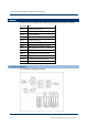
Example Controller Configuration This example controller has two 9110 processor modules and supports 8 digital inputs and 8 digital outputs. Note: The '9801' and '9851' illustrated are simplex termination assemblies for the I/O modules and provide the connections for the field elements. This controller has the following physical layout: the two I/O modules are installed to the right of the processor base unit, which is IO Bus 1.
Demo Unit User Manual (AADvance Controller) The slot and bus numbers must be the same as the actual physical position of the installed modules. Therefore, for this example you would allocate I/O modules as follows: A 9401 module to the empty slot 1 on IO Bus 1 A 9451 module to the empty slot 2 on IO Bus 1. Assign I/O Modules to I/O Bus Slots If you are assigning a single module you can assign the module to any empty I/O bus slot.
4) Select the required module, then move the cursor to the right and select the number of modules you require. 5) Repeat this for all the modules you want to configure. Clear an I/O Bus Slot To clear an I/O bus slot do the following: 1) Select the Equipment tab. 2) Right-click to select Clear Slot. The module will be removed from the slot. The slot will now display as Empty ready to be re-assigned a module. Note: The channel variable wiring will automatically be unwired. Document: 553850 Issue 1.
Demo Unit User Manual (AADvance Controller) Move a Module to a Different Slot To move an assigned module to a different slot do the following: 1) Select the Equipment tab. 2) Right-click to select the Move To option. 3) Move the cursor to the right and select the IO Bus 1 Position you want to move to. The module is automatically re-assigned to the selected slot. Note: The channel variable wiring will move with the module to the new slot and is automatically renumbered.
Wire Status Variables to I/O Modules You can wire a variable to an I/O module so the application can receive status information from the module. The AADvance Workbench provides a structure (T9K_TA_GROUP_STATUS) for module status information. To wire a status variable to an I/O module do the following: 1) Declare a variable in Dictionary. Use the type T9K_TA_GROUP_STATUS and make sure that the direction is set to input. 2) Select a module from the I/O bus. The unwired term appears in the Variable field.
Demo Unit User Manual (AADvance Controller) T9K_TA_GROUP_STATUS (I/O Module Status Information) The data structure for module status information (T9K_TA_GROUP_STATUS) provides the elements detailed in the table. Note: The controller interrogates an I/O module (designated 'X' in the table) according to the physical arrangement of the module and its position in a group. A simplex module is designated as module A; a duplex module as A or B and a triplicated module as A, B or C.
.XSDN BOOL Shutdown status Reports that module X requires manual intervention (pressing the Fault Reset button) before values can be reported TRUE: the module needs manual intervention .XPOS INT Position Reports the slot number of module X (1 to 24) (†) Note: (†) Slots are numbered 1 to 24 on both buses; the slot location (.LOC) and position (XPOS) do not identify the bus.
Demo Unit User Manual (AADvance Controller) Wire Variables to Digital Input Channels To wire variables to digital input channels do the following: 1) Select a digital input module on the I/O Bus. The module status variable that you assigned will appear in the Variable field. 2) Select the channel that you want to wire to a variable. 3) Click the button adjacent to the Channel Variable fields. 4) Choose a data structure from the three options displayed: Simple, Compact, Full.
Wire Variables to Analogue Input Channels To wire variables to analogue input channels do the following: 1) Select an analogue input module on the I/O bus. The module status variable that you assigned will appear in the Variable field. 2) Select the channel that you want to wire to a variable. 3) Click the button next to the channel variable fields. 4) Choose a data structure from the three options displayed: Simple, Compact, Full. The Select Variables dialog box is displayed.
Demo Unit User Manual (AADvance Controller) Wire Variables to Digital Output Channels To wire variables to digital output channels do the following: 1) Select a digital output module on the I/O bus. The module status variable appears in the Variable field. 2) Select the channel that you want to wire to a variable. 3) Click the button next to the Channel Variable fields. 4) Choose a data structure from the three options displayed: Simple, Compact, Full.
TK9_DI_COMPACT and TK9_DI_FULL (Digital Inputs) The two data structures for digital input channels (TK9_DI_COMPACT and TK9_DI_FULL) provide the elements detailed in the tables. Table 10: TK9_DI_COMPACT Structure for Digital Inputs Identifier Type Description Remarks .DI BOOL Input state TRUE: input voltage above threshold T6 FALSE: input voltage below threshold T5 .
Demo Unit User Manual (AADvance Controller) Note: (†) Discrepancy can only be reported TRUE when two or three modules are active in a group. (††) The voltage element cannot report values below 0mV. Faulted State for Digital Inputs A digital input channel is faulted (the state reports a value of 7) when the channel is incapable of reporting a voltage within a safety accuracy specification of 10% of the full scale measurement of the 24V dc supply (2.4V).
Define Thresholds for a Digital Input Module To define your own threshold values do the following: Document: 553850 Issue 1.
Demo Unit User Manual (AADvance Controller) 1) Select the Thresholds tab on the module editor. A set of default values is shown in the threshold fields. 2) To enter your own values select the Use Custom Thresholds box, enter your own values in the threshold fields, click Apply. 3) To restore the default values, Click Default then de-select the Use Custom Thresholds, click Apply. 5-16 Document: 553850 Issue 1.
Default Thresholds for Digital Inputs The default threshold values for digital inputs are for a standard (non-line monitored) 24V dc digital input channel. The default values are given in the table. Default Threshold Values for the 9401 Digital Input Module Document: 553850 Issue 1.
Demo Unit User Manual (AADvance Controller) Configuring Analogue Inputs You can wire analogue input channels to the following variable type and data structures: REAL (the gives a floating-point value representing 4 to 20mA) TK9_AI_Compact (provides three elements) TK9_AI_Full (six elements) The structures provide additional information about the input, such as discrepancy status. You can also configure analogue inputs to operate with HART devices, and define custom thresholds.
.CNT INT Raw count A count representing the current on the channel in units of 1/256mA 0 represents 0mA; 5,120 represents 20mA Accurate to within ± 13 counts, equivalent to ± 0.05mA .LF BOOL Line fault TRUE: state (.STA) is 1, 5, 6 or 7 FALSE: state (.STA) is 2, 3 or 4 .DIS BOOL Discrepancy TRUE: there is a discrepancy in current greater than 2% between the channels of two or three modules in a redundant configuration (†) .
Demo Unit User Manual (AADvance Controller) About HART The AADvance controller is the first Rockwell Automation controller to include integrated support for HART (Highway Addressable Remote Transducer) communications. There is no need for separate HART interfaces. The AADvance Workbench supports HART on analogue input channels; the system implements revision 5 of the HART specification. The application program can use HART information to monitor and respond to device conditions.
2) Go to the Equipment Tree View and select the analogue input module. Click on the HART tab. 3) Select a Channel, click . 4) Choose a variable from the Dictionary list, click OK. 5) Return to the Equipment Tree View, select the channel and click on the HART tab; then put a tick in the box labeled Enable HART on this Channel, click Apply. 6) Repeat this procedure for the other inputs that will use HART-enabled devices.
Demo Unit User Manual (AADvance Controller) .DEVICE BYTE Device status (†) Bit 7: field device malfunction Bit 6: configuration changed Bit 5: cold start Bit 4: more status available Bit 3: analogue output current fixed Bit 2: analogue output saturated Bit 1: non-primary variable out of limits Bit 0: primary variable out of limits Note: (†) The device status byte mimics the HART field device status. Appendix E of the HART Application Guide gives details.
Define Thresholds for an Analogue Input Module To define your own threshold values do the following: Document: 553850 Issue 1.
Demo Unit User Manual (AADvance Controller) 1) Select the Thresholds tab on the module editor. A set of default values is shown in the threshold fields. 2) To enter your own values select the Use Custom Thresholds box, enter your own values in the threshold fields, click Apply. Note: You can enter the values in counts (the default units) or in milliamps. To specify a value in milliamps, append 'mA' to the value; the AADvance Workbench will convert it into counts.
Default Thresholds for Analogue Inputs The default threshold values for analogue inputs are for a standard (non-line monitored) 24V dc analogue input channel. The default values are given in the table. Table 15: Default Threshold Values for the 9431 Analogue Input Module Document: 553850 Issue 1.
Demo Unit User Manual (AADvance Controller) Configuring Digital Outputs You can wire digital output channels to the following variable type and data structures: BOOL (the gives the commanded state) TK9_DO_Compact (provides three elements) TK9_DO_Full (seven elements) The structures provide additional information about the output, such as line fault status and discrepancy status.
.DIS BOOL Discrepancy TRUE: there is a discrepancy in current greater than 1% between the channels of two modules in a redundant configuration (†) .CF BOOL Channel fault TRUE: module diagnostics detect a fault in the channel electronics or firmware (state = 7) .V UINT Voltage Reports the channel voltage at the output terminals, in units of millivolts and with an accuracy of ± 500mV (††) .
Demo Unit User Manual (AADvance Controller) Overcurrent Protection for Digital Outputs The AADvance controller has three mechanisms to protect its digital output channels: Inrush current protection Short circuit protection for energized channels Short circuit protection for de-energized channels The controller tolerates inrush currents so that its digital outputs can energize capacitive loads without causing the controller to report a short circuit.
Faulted State for Digital Outputs A digital output channel is faulted (the state reports a value of 7) when normal operation or diagnostics tests have identified a specific fault condition. A single identified fault condition thus results in a state value of 7.
Demo Unit User Manual (AADvance Controller) Digital Output Advanced Channel Settings Each output channel from the 9451 digital output module supports the set of control parameters detailed in the table.
About Status Variables for Digital Output Modules The 9451 digital output module provides a number of status variables that are available to the application. The 9451 Variables Editor presents the variables in two collections, which it calls 'racks': Status Booleans, and Power Status Integers. Wire Status Variables to a Digital Output Module To wire a status variable to a digital output module do the following: 1) Navigate to the digital output module in the equipment tree view.
Demo Unit User Manual (AADvance Controller) The 9451 Variables Editor dialog box opens. 2) Select the relevant rack. The editor displays a list of associated variables. 3) Select the variable to be unwired, click the X button. 4) Click Apply. The variable will be unwired. Note: Select the Unwire All button and click Apply to disconnect all of the wired variables in the rack.
Field Power Status Integers The variables in the rack of field power status integers (all DINT) provide information to the application about the field power supplies to a group of digital output modules. Group Field Power Current Direction: input to application from controller Type: DINT Values: 0 to 8,000mA or greater (limited by capacity of DINT variable) Description: Reports the total current that all the active digital output modules in a group are drawing from the field power supply.
Demo Unit User Manual (AADvance Controller) B Module Field Power Voltage 2 Direction: input to application from controller Type: DINT Values: 0 to 48,000mV or greater (limited by capacity of DINT variable) Description: Reports the voltage from the field power supply, for the specified module and field power input. Accuracy is ± 500mV. 5-34 Document: 553850 Issue 1.