Allen-Bradley IMC S Class Compact Motion Controller (Cat. No.
Important User Information Because of the variety of uses for the products described in this publication, those responsible for the application and use of this control equipment must satisfy themselves that all necessary steps have been taken to assure that each application and use meets all performance and safety requirements, including any applicable laws, regulations, codes and standards.
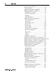
Table of Contents i Preface Who Should Use this Manual ........................ P-1 Purpose of this Manual .................................. P-1 Safety Precautions .......................................... P-1 Contents of this Manual ................................. P-2 Related Documentation ............................... P-3 Product Receiving & Storage Responsibility. P-3 Allen-Bradley Support ................................... P-3 Local Product Support .................................
ii Table of Contents Chapter 3 – Technical Overview Digital Control Loop ...................................... 3-1 Encoders ......................................................... 3-2 Encoder Counter ............................................ 3-3 Software Feedback Calculations.................... 3-4 Servo Amplifiers and Motors ......................... 3-5 High Level Motion Functions ........................ 3-6 Indexing and Jogging ................................... 3-7 Backlash Compensation .....
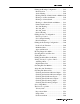
Table of Contents iii Serial Communication Protocol ................. 4-15 Connecting RS-232 Devices ...................... 4-16 Connecting RS-422 Devices ...................... 4-18 Connecting Encoders ................................... 4-19 AB 1391B-ES & 1391-DES Drives .......... 4-20 AB 845F, 845H, & 845T Encoders ........... 4-20 AB 845K Encoders .................................... 4-21 AB 845P Encoders ..................................... 4-21 Other Encoders ......................................
iv Table of Contents Application Setup Menu ................................ 5-5 Upload Inhibit .............................................. 5-6 Editing the AxisLink Configuration .............. 5-6 Editing the DH-485 Configuration ................ 5-6 Maximum Node Address............................. 5-7 Network Node Address ............................... 5-7 Baud Rate .................................................... 5-7 Token Hold Factor .......................................
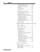
Table of Contents v Editing the Homing Configuration .............. 5-29 Home Position ........................................... 5-29 Active Homing .......................................... 5-30 Homing Without a Limit Switch or Marker 5-30 Homing to an Encoder Marker .................. 5-30 Homing to a Limit Switch ......................... 5-31 Homing to a Limit Switch and Marker...... 5-32 Limit Switch Contacts ............................... 5-32 Absolute Homing......................................
vi Table of Contents Self-Tuning the Servo Gains ........................ 5-60 Using the Position Error Integrator ........... 5-66 Using Velocity Feedforward ...................... 5-66 Tuning Faults ............................................... 5-67 Aborted by Escape! ................................... 5-67 Encoder Fault! ........................................... 5-67 Hit Hardware Overtravel Limit! ................ 5-67 Position Error Tolerance Exceeded! .......... 5-68 Drive Fault Detected! ......
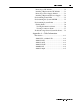
Table of Contents vii Removing a CPU Module............................ 7-2 Installing a Replacement CPU Module ....... 7-3 Removing a Power Supply Module ............. 7-3 Installing a Replacement Power Supply ..... 7-4 Understanding Status LEDs ........................... 7-5 Understanding the System OK LED .............. 7-5 Understanding System Faults ......................... 7-6 Finding Faults .............................................. 7-6 Viewing Instantaneous Status....................
viii Table of Contents Publication 999-122 January 1997
Preface P-1 Preface Read this preface to familiarize yourself with the rest of the manual. This preface covers the following topics: • • • • • Who Should Use this Manual who should use this manual the purpose of this manual general safety precautions receiving and storage information Allen-Bradley support Use this manual if you are responsible for designing, installing, programming, or troubleshooting the Allen-Bradley IMC S Class Compact.
P-2 Preface ! ATTENTION: An incorrectly applied or installed Compact can result in component damage or a reduction in product life. Wiring or application errors, such as undersizing the motor, incorrect or inadequate AC supply, or excessive ambient temperatures can result in malfunction of the product. ATTENTION: This product contains ESD (Electrostatic Discharge) sensitive parts and assemblies. Static control precautions are required when installing, testing, servicing, or repairing this assembly.
Preface P-3 Related Documentation The following documents contain additional information concerning related Allen-Bradley products. To obtain a copy, contact your local Allen-Bradley office or distributor. For Read This Document Document Number A description and specifications for the Compact Compact Motion Controller Product Data 4100-2.3 A user guide for GML programming to be used with the Compact.
P-4 Preface Local Product Support Contact your local Allen-Bradley representative for: • • • • sales and order support product technical training warranty support support service agreements Technical Product Assistance If you need to contact Allen-Bradley for technical assistance, please review the information in the Troubleshooting chapter first. Then call your local Allen-Bradley representative.
Chapter 1 Safety Read This Manual Read and understand this instruction manual. It provides the necessary information to allow you to install, connect, and set up your IMCñS/23x for safe, reliable operation. ! ATTENTION: DANGEROUS MACHINERY! Operation and maintenance of automatic equipment involves potential hazards. Control Operators, Setup Personnel, and Programmers should each take precautions to avoid injury. Injury and entanglement may occur if hands and limbs come in contact with moving machinery.
1-2 Safety Publication 999-122 - January 1997
Chapter 2 Introduction IMC-S/23x Description The IMC-S/23x is a compact, rugged, microprocessor-based two- or four-axis servo motion controller. By including the logic and field power supplies, the IMC-S/23x provides a completely programmable, stand-alone motion and logic controller suitable for a wide variety of industrial applications.
2-2 Introduction A dedicated serial port–which can be field-configured for RS-232, RS-422, or Allen-Bradley DH-485 communications–is provided for the man-machine interface (MMI). Connection of the MMI device is via an AT-compatible DB-9 connector (RS-232 or RS-422) or RJ-45 connector (DH-485), both located on the front panel.
Introduction 2-3 • Wide position, speed, acceleration, and deceleration ranges for • • • • • • • • • • • • • • • • • • • precise control. Separately programmable acceleration and deceleration rates for maximum versatility. Trapezoidal, parabolic, and S-curve velocity profiles. Rotary mode with electronic unwind allows unlimited position range for rotary axes. Merge motion function allows seamless transition between all types of motion.
2-4 Introduction • AxisLink option allows real-time axis coordination between controllers for distributed, multi-axis systems. • Non-volatile storage (write-locked battery-backed RAM) of application program, setup parameter and default variable values. • Memory Lock keyswitch on front panel prevents accidental or unauthorized changes to application program, default setup parameters, and default variable values.
Introduction 2-5 IMC S/23x Pre-Engineered Cable Assemblies Catalog Number 4100-CCF1 or 4100-CCF3 4100-CCS15F 4100-CCAQB 4100-CCA15F 4100-CCW15F 4100-RCS3T Mechanical Specifications Used to Connect. . . Flex I/O Servo and Feedback 1391B-ES or 1391-DES Dedicated Discrete I/O CPU Watchdog REC Interface Length (ft) (m) 1 3 15 15 15 3 0.3 1 4.5 4.5 4.5 1 Number Required 1 per S Class 1 per Axis 1 per Axis 1 per Axis 1 per S Class 1 per Axis Front Panel Layout (IMC-S/23x-RL model shown.
2-6 Introduction Mounting and Clearance Dimensions General Specifications Motion Control Microprocessor Number of Controlled Axes Application Storage Data Storage Number of User Variables Number of Electronic Cam Points Intel 80960SB @ 16 MHz. 2 (Axis 0 and Axis 1) IMC-S/232...models. 4 (Axis 0, 1, 2, and 3) IMC-S/234...models. Write-lockable battery-backed RAM (Random-Access Memory) with 10 year (minimum) battery life for application program (32K) and setup parameter values.
Introduction 2-7 Environmental Specifications Storage Temperature Operating Temperature Maximum Humidity -40°C to 70°C (-40°F to 158°F). 0°C to 50°C (32°F to 122°F). 95% non-condensing. Electrical Specifications AC Power Input AC Fuse I/O Power Input I/O Fuse 90 - 132 or 175 - 264 Volts AC, 47 - 63 Hz, 3 Amperes maximum. 3A Dual Element Time Delay (Slow Blow) 1/4 x 11/4 18 - 36V DC, 3A maximum (24V nominal).
2-8 Introduction Servo Output Specifications Number of Servo Drive Outputs Type of Output Output Range Resolution Output Impedance Output Offset 2 (Axis 0 and Axis 1) IMC-S/232...models. 4 (Axis 0, 1, 2, and 3) IMC-S/234...models. Isolated analog voltage or current; individually field-configurable via internal switch for each axis. ±10 Volts DC or ±150 µA (minimum). 16 bits, 305 µV or 4.58 µA per bit. 220Ω resistive for voltage output; 56Ω maximum load impedance for current output. ±80 µV maximum.
Introduction 2-9 Serial I/O Specifications Number of Serial Channels Channel Type Information Code Baud Rate Number of Start Bits Number of Stop Bits Word Length Parity Duplex Data Synchronization Front-Panel Connectors RS-422 Termination 2 (Serial Port A and Serial Port B). Optically isolated RS-232C or RS-422; each channel individually configurable via internal switch. ASCII (American Standard Code for Information Interchange). User-selectable up to 128k Baud (RS-422). User-selectable up to 115.
2-10 Introduction Flex I/O Compatibility Specifications Maximum Number of Flex I/O Modules Compatible Modules S Class Interface 8. 1794-IB16 16 24V DC Discrete Inputs 1794-IA8 8 115V AC Discrete Inputs 1794-IE8 8 Current/Voltage Analog Inputs 1794-OB16 16 24V DC Discrete Outputs 1794-OA8 8 115V AC Discrete Outputs 1794-OE4 4 Current/Voltage Analog Outputs 1794-IE4XOE2 4 Current/Voltage Analog Inputs 2 Current/Voltage Analog Outputs Direct-no 1794-ASB or other adapter required.
Introduction 2-11 Servo Gain Units IMC-S/23x Servo Gain Units Gain Description Units P Proportional Gain Counts per Millisecond Count of Error I Integral Gain Counts per Millisecond2 Count of Error V Velocity Gain Millivolts Count per Millisecond F Feedforward Gain Counts per Millisecond Count per Millisecond Deadband Compensation Offset Compensation Remote I/O Adapter Specifications Baud Rate Rack Address Rack Width I/O Group Address Volts Volts IMC-S/23x-R and IMC-S/23x-RL models only
2-12 Introduction Number of Discrete I/O Bits 12 dedicated inputs, 12 dedicated outputs, User-defined as shown below: IMC-S/23x Remote I/O Adapter Number of User-Defined Discrete I/O Bits Maximum Block Transfer Length Rack Width Inputs Outputs 1/4 1/2 3/4 Full 4 36 68 100 4 36 68 100 64 words (128 bytes).
Introduction AxisLink Specifications Baud Rate Cable Type Cable Length Number of Motion Controllers Addressing Number of Virtual Master Axes IMC-S/23x-L and IMC-S/23x-RL models only.
2-14 Introduction Number of Discrete I/O All configurations Discrete I/O Response All configurations 112 inputs maximum total and 16 user-definable outputs per motion controller. Any motion controller can read the 16 discrete outputs of any other motion controller, giving a maximum total of 7 x 16 = 112 discrete inputs per motion controller.
Chapter 3 Technical Overview Digital Control Loop Each axis of the IMC-S/23x utilizes a powerful Nested Digital Servo Control Loop to provide servo positioning control and compensation of a servo actuator. The servo actuator can be a DC motor, a brushless DC motor, an AC motor (with the appropriate drive electronics), or a hydraulic cylinder or motor.
3-2 Technical Overview A functional block diagram of the Nested Digital Servo Loop is shown below. The following sections discuss, in detail, each block in this diagram. Encoders The IMC-S/23x interfaces to rotary or linear quadrature-type incremental encoders to provide both position and velocity feedback. The most common type of such encoders are optical; they utilize a light source and an alternately clear and opaque disc or scale to generate their output.
Technical Overview 3-3 Often a third output channel is available from the encoder. This so-called "marker" output is also known as Channel Z, 0, or C. The marker output from an encoder is a pulse that occurs at one specific point on the encoder disc (rotary encoders) or slide (linear encoders). Therefore, the marker may be used to establish a precise absolute position reference. Note that for rotary encoders, the marker provides a position reference within one revolution of the encoder.
3-4 Technical Overview Software Feedback Calculations Every servo sample period, the IMC-S/23x microprocessor also does a complete position feedback calculation for each axis by first computing the difference between the actual position and the command position. This quantity is called the Position Error. The intent of every closed loop position servo system is to drive this position error to zero.
Technical Overview 3-5 Finally, drive offset compensation is provided to allow compensating for the inevitable offset and drift in analog servo amplifiers. Drive offset compensation adds a programmable value to the magnitude of the servo output signal. Each of the gain terms mentioned above has a unique influence on the closed loop dynamics of the system. By adjusting the P, I, and V gains, it is easy to tailor the system dynamics to meet specific needs.
3-6 Technical Overview High Level Motion Functions Because servo action forces the actual position to track the command position, sophisticated indexing, jogging, and electronic gearing functions are easily implemented through software control of the command position. These high level motion functions are shown below and explained in the following paragraphs.
Technical Overview 3-7 Indexing and Jogging The indexer moves the axis using either a trapezoidal, parabolic, or S-Curve (controlled jerk) velocity profile. Axis velocity, acceleration, and deceleration are completely programmable. The trapezoidal profile is the most common type of move and results in a smooth acceleration to the desired speed and a smooth deceleration to the desired destination position.
3-8 Technical Overview Electronic gearing is accomplished by first reading the master axis’ actual position and computing the distance increment from the previous reading. This increment is then multiplied by a programmable gear ratio and added to the slave axis’ command position. In this way the slave axis is forced to track the master axis according to the specified gear ratio. The slave axis may be programmed to move in the same or the opposite direction from the master axis.
Technical Overview 3-9 Velocity feedforward is very useful in electronic gearing applications, since no position error between the master and slave axes exists with mechanical gears. Using velocity feedforward also allows the position loop integrator (I Gain) to respond more quickly to changes in speed. CPU Watchdog The IMC-S/23x provides a CPU Watchdog that monitors the health of the motion control microprocessor.
3-10 Technical Overview DH-485 Communication The IMC-S/23x communicates with other devices over DH-485 by reading and writing data into and out of data files. Data from local files (in the motion controller) is transferred to and from remote files (in other devices). In the motion controller, up to 13 different local files of five different types can be used. Each type of file contains a different number of elements and is equivalent to a different SLC file type as shown below.
Technical Overview 3-11 Drive Fault Output The drive fault inputs may be connected to the fault outputs (if provided) on the amplifiers for each axis. This allows the IMC-S/23x to react to a fault in the amplifiers themselves. Like the other discrete inputs, the drive fault input may be enabled and disabled from the application program, and may be configured to operate with active-high or active-low drive fault outputs.
3-12 Technical Overview General Purpose Discrete I/O The IMC-S/23x provides a direct connection to Allen-Bradley Flex I/O for use as general-purpose I/O. The Flex I/O modules which may be used with S Class motion controllers are shown in the table below.
Chapter 4 Installation and Hookup Introduction The IMC-S/234 provides four physical axes called Axis 0, 1, 2, and 3. The IMC-S/232 provides two physical axes (Axis 0 and Axis 1), and therefore only two servo amplifiers are required for this unit. Connections for each axis are made to separate but identical connectors on the top and bottom panels of the unit.
4-2 Installation and Hookup As shown below, the servo drive and feedback devices attach to the bottom panel of the IMC S Class Compact while the axis-specific (dedicated) I/O devices attach to the top panel. Power input terminal blocks are on the right side of the unit.
Installation and Hookup Complying with European Union Directives 4-3 The information contained in this document pertains to the following Allen-Bradley products: • • • • • • • • 4100-234-RL 4100-234-R 4100-234-L 4100-234 4100-232-RL 4100-232-R 4100-232-L 4100-232 If these products are installed within the European Union or EEA regions and have the CE mark, the following regulations apply.
4-4 Installation and Hookup To meet CE requirements, the following additions are required: • You must mount the Bulletin 4100 Compact in an IP 54 rated metal • • • • enclosure on a metal panel. You must bond all equipment. You must use the specified Allen-Bradley cables. The IMC-S/23x is designed to function without maintenance when operated in the environment specified in this manual. Under normal conditions, the IMC-S/23x should not require any periodic maintenance.
Installation and Hookup 4-5 Figure 5.1 Suggested Bulletin 4100 Compact Motion Control System Configuration for Meeting CE Requirements A/C and I/O fuse types: 3A Dual Element Time Delay (Slow Blow) (1/4 in. by 1 1/4 in.). Important: Input power is to be wired in accordance with local regulations.
4-6 Installation and Hookup Installing the IMC-S/23x The IMC-S/23x should be mounted to a panel inside an electrical cabinet or enclosure. For best performance, it should be mounted as close as practical to the servo drives with which it is being used. This minimizes the length of cable required to interconnect the units, thus minimizing the risk of electrical noise pickup. See the Introduction section of this manual for mounting and clearance dimensions.
Installation and Hookup Configuring the IMC-S/23x 4-7 Before applying power to the IMC-S/23x or connecting external devices, the unit must be configured for your application. The IMC-S/23x is configured via switches on the motion controller and power supply modules inside the unit, as shown in the table below. IMC-S/23x Configuration Switches To Configure... Use This Switch... On This Module Serial Ports Axis 0 and 1 Regist. Inputs Axis 2 and 3 Regist.
4-8 Installation and Hookup Configure the Serial Ports Serial port A may be independently configured for RS-232 or RS-422 operation and serial port B may be independently configured for RS-232C, RS-422, or DH-485 operation via switch SW1 on the motion controller module inside the IMC-S/23x. If RS-422 or DH-485 is selected, the port may also be configured to use or not use a termination resistor. The serial port configuration switch layout is shown below.
Installation and Hookup 4-9 RS-422 220Ω RS-422 Term RS-422 220Ω RS-422 Term DH-485 220Ω DH-485 Term To configure either serial port for RS-422 communications, carefully move the first (port A) or second (port B) pair of switches to their up positions using a pen, small screwdriver, etc. For example, the figure below shows serial port A configured for RS-232 and serial port B configured for RS-422.
4-10 Installation and Hookup Port B RS-232 No 220 Ω RS-422 Term. RS-232 No 220 Ω RS-422 Term. RS-232/422 No DH-485 Term. SW1 RS-422 220 W RS-422 Term. RS-422 220 W RS-422 Term. DH-485 220 W DH-485 Term. To configure serial port B for DH-485 communications, carefully move the rightmost pair of switches to their up positions using a pen, small screwdriver, etc. For example, the figure below shows serial port A configured for RS-232 and serial port B configured for DH-485.
Installation and Hookup 4-11 Select the Registration Input Voltage Each axis of the IMC-S/23x may be individually configured to interface directly with either 5V or 24V DC registration sensors via switches on the motion controller module. SW2 on the main board selects the registration input voltage for axes 0 and 1, and SW1 on the expander board selects the registration input voltage for axes 2 and 3.
4-12 Installation and Hookup Select the Encoder Power Voltage The IMC-S/23x may be configured to provide either 5V or 12V DC power (at 1 Ampere total maximum) for the axis feedback encoders via switch SW5 on the power supply module. SW5-1 selects the encoder power voltage for axes 0 and 1, and SW5-2 for axes 2 and 3. Regardless of the encoder power voltage selected, however, the encoder outputs must be 5V (TTL) level signals.
Installation and Hookup 4-13 If you are using an Allen-Bradley 845 series incremental encoder, use the table below to determine the proper encoder power voltage switch setting. IMC-S/23x Encoder Voltage Switch Settings for Allen-Bradley Encoders Allen-Bradley Encoder Model SW5 845F-SJxZ14-xxYx... 845F-SJxZ24-xxYx... Down (5V) Up (12V) 845H-SJxx14xxYx... 845H-SJxx24xxYx... Down (5V) Up (12V) 845K-SAxZ14-xxY3 845K-SAxZ24-xxY3 Down (5V) Up (12V) 845P-SHC14-xx3 Down (5V) 845T-xx12Exx...
4-14 Installation and Hookup Select the Servo Output Format Each axis of the IMC-S/23x may be individually configured to provide either a ±10V (voltage) or ±150 mA (current) servo output signal via switches on the power supply module. SW3 selects the servo output format for axes 0 and 1, and SW4 for axes 2 and 3. The IMC-S/23x is shipped from the factory configured for ±10V servo output for all axes (all switches up), as shown below.
Installation and Hookup Serial Communications Devices 4-15 The IMC-S/23x provides two optically-isolated serial ports called Serial Port A and Serial Port B. These ports are accessible through the 9-pin AT-compatible DB-9 connectors on the front panel. Both front panel connectors are pinned out identically, so connection to either port is the same. ! ATTENTION: Do not connect anything to Serial Port B if you are using DH-485.
4-16 Installation and Hookup Connecting RS-232 Devices When an IMC-S/23x serial port is configured for RS-232 operation (see Configuring the IMC-S/23x earlier in this section), RS-232C compatible serial communications devices may be connected to it using readily-available RS-232C cables. To prevent damage to the IMC-S/23x or the serial device, make sure that the serial port is configured for RS-232 operation before connecting RS-232 compatible devices.
Installation and Hookup 4-17 If you are making an RS-232C cable, only four conductors are required. Construct the cable as shown below, making sure to use the correct mating connector for your PC or terminal. The mating connector for the IMC-S/23x is a standard male 9-pin D-type (AMP P/N 205204-1). Most serial communication devices (PCs, PC compatibles, and terminals) use one of two types of RS-232C connector.
4-18 Installation and Hookup Connecting RS-422 Devices When an IMC-S/23x serial port is configured for RS-422 operation (see Configuring the IMC-S/23x earlier in this section), RS-422 compatible serial communications devices may be connected to it using pre-made RS-232C/RS-422 cables. To prevent damage to the IMC-S/23x or the serial device, make sure that the serial port is configured for RS-422 operation before connecting RS-422 compatible devices.
Installation and Hookup 4-19 If you are making an RS-422 cable, five conductors are required. Construct the cable as shown below, making sure to use the correct mating connector for your PC or terminal. The mating connector for the IMC-S/23x is a standard male 9-pin D-type (AMP P/N 205204-1). Be sure that the TxD+/- and RxD+/- pairs are twisted as shown above for best noise immunity.
4-20 Installation and Hookup Allen-Bradley 1391B-ES and 1391-DES Drives If you are using 4100-CCAQB pre-engineered cable assemblies from Allen-Bradley to connect the IMC-S/23x to Allen-Bradley 1391B-ES or 1391-DES AC servo drives, select 5V encoder power (the factory setting) and refer to Appendix A for connection information.
Installation and Hookup 4-21 Allen-Bradley 845K Encoders If you are using Allen-Bradley 845K-SAxZx4-xxY3 incremental encoders, connect them to the IMC-S/23x using a separate 4100-CCSxxF pre-engineered cable assembly for each axis as shown below. Note that a user-supplied terminal block (TB) or intermediate connector is required to connect the 845K’s integrated cable to the 4100-CCSxxF cable assembly.
4-22 Installation and Hookup Note that a user-supplied terminal block (TB) or intermediate connector is required to connect the 845P’s integrated cable to the 4100-CCSxxF cable assembly. Other Encoders If you are not using Allen-Bradley 1391B-ES or 1391-DES servo drives or Allen-Bradley 845 encoders, connect each encoder to the IMC-S/23x using a separate 4100-CCSxxF pre-engineered cable assembly for each axis as shown below.
Installation and Hookup 4-23 Allen-Bradley 1391B-ES and 1391-DES Drives If you are using 4100-CCAQB pre-engineered cable assemblies from Allen-Bradley to connect Allen-Bradley 1391B-ES or 1391-DES AC servo drives to the IMC-S/23x, select voltage servo output format (the factory setting) and refer to Appendix A for connection information.
4-24 Installation and Hookup Connecting Hydraulic Valves The IMC-S/23x can also be used with any commercially available hydraulic servo or proportional valve that accepts a ±150 mA analog input signal. Each axis of the IMC-S/23x may be individually configured to provide either a ±10V (voltage) or ±150 mA (current) servo output signal as explained in Select the Servo Output Format earlier in this section. For hydraulic valves, ensure that the appropriate axes are set for current output.
Installation and Hookup Connecting Axis-Specific Discrete I/O 4-25 The IMC-S/23x provides home and overtravel limit switch inputs and a drive fault input for each axis. These axis-specific discrete inputs are optically isolated and filtered to eliminate switch bounce. In addition, the IMC-S/23x provides a normally open relay contact drive enable output for each axis. Connect axis-specific I/O to the IMC-S/23x using a separate 4100-CCAxxF pre-engineered cable assembly for each axis as shown below.
4-26 Installation and Hookup The Drive Enable Outputs Many servo amplifiers provide a drive enable/disable input which can be used by the IMC-S/23x to disable the drive whenever feedback is turned off. The drive enable outputs (one for each axis) of the IMC-S/23x provide a normally open relay contact capable of conducting up to 1 Ampere at up to 40V DC (24V DC nominal) for this purpose.
Installation and Hookup Connecting Registration Sensors 4-27 The IMC-S/23x provides a high-speed optically isolated registration input for each axis. These registration inputs require 2.5 mA at 5V DC (each) to operate. ! ATTENTION: Set the registration switches for 5V or 24V sensors before connecting registration devices.
4-28 Installation and Hookup ! ATTENTION: Use a clean 24V power supply for 24V sensors; do not use the general purpose I/O power supply. Use a clean 5V power supply for 5V registration sensors or a clean 24V power supply for 24V sensors. Do not use the 24V DC power supply connected to the IMC-S/23x for the axis-specific discrete I/O. Using the Registration Inputs The registration inputs on the IMC S Class are the most sensitive discrete inputs on the motion controller.
Installation and Hookup Connecting the CPU Watchdog 4-29 The IMC-S/23x provides a fail-safe CPU watchdog with relay-contact outputs for connecting into your machine’s start/stop string or other protective circuit. Form-C (NO and NC) contacts are provided to allow external equipment to be disabled in the event of a control malfunction. The CPU watchdog relay is activated during normal operation and deactivates when there is a malfunction.
4-30 Installation and Hookup Connecting Flex I/O Flex I/O modules connect directly to the IMC-S/23x using a 4100-CCF1 or 4100-CCF3 pre-engineered cable assembly. Plug the mini-D connector end of the 4100-CCF1 or 4100-CCF3 into the connector marked Flex I/O on the left of the top panel of the IMC-S/23x and the other end into the first Flex I/O module as shown in the general connection figure at the beginning of this section.
Installation and Hookup Connect the AC Power 4-31 The IMC-S/23x requires 3 Amperes (maximum) at 90 - 132 or 175 264 Volts AC (auto switching), 47 - 63 Hz, single-phase. This is compatible with the AC mains power in all countries. Connect AC power to the AC power input (four position) terminal block on the right side of the IMC-S/23x as shown below. ! ATTENTION: The IMC-S/23x must be connected to earth ground as shown above for proper operation.
4-32 Installation and Hookup Connecting Remote I/O (Optional) IMC-S/23x-R and IMC-23x-RL models include a Remote I/O (RIO) Adapter for connection to an Allen-Bradley PLC. On these models, the RIO cable is connected using a 3-terminal pluggable terminal block to either channel A or channel B of the Remote I/O Adapter front panel. The front panel of the Remote I/O Adapter is shown below.
Installation and Hookup 4-33 Plug the terminal block into the channel (A or B) on the RIO adapter which you wish to use for RIO communications. Either channel can be used–the selection is made in the Application Setup Menu. See the Setup section of this manual for information on configuring RIO operation.
4-34 Installation and Hookup ! ATTENTION: Even though AxisLink and RIO use the same cable, connections are not interchangeable. Do not mix RIO and AxisLink connections or neither link will work properly. The AxisLink option can be operated in either of two configurations depending upon the cable length required between controllers. Refer to the AxisLink specifications in this manual for more information on the differences between the two configurations.
Installation and Hookup 4-35 AxisLink Settings for Extended Length AxisLink Operation Switch 1 (SW1) on the AxisLink board must be set to the EXTENDED setting (away from the edge of the board). Jumper 5 (J5), labeled XTEND on the board, must be in place across both J5 pins if using onboard cable termination. Jumper 6 (J6) on the board should not be connected.
4-36 Installation and Hookup Extended Configuration Diagram AxisLink Terminal Block Yellow 300 * Shield Extended AxisLink Cable Black * Install termination resistor only if this is the first or last physical module on the AxisLink and if the onboard cable termination resistors are not used. Belden 9182, Carol C8014 or equivalent. Plug the terminal block back into channel A on the front panel of the AxisLink option.
Installation and Hookup ! 4-37 ATTENTION: Do not connect anything to Serial Port B of the IMC-S/23x if you are using DH-485 communications. When DH-485 is used, serial port B on the motion controller is used for DH-485 communication and the normal built-in operator interface functions of the IMC S Class are unavailable. When DH-485 is used, do not make any connections to serial port B on the motion controller.
4-38 Installation and Hookup Publication 999-122 - January 1997
Chapter 5 Understanding IMC-S/23x Setups This chapter shows you how to program your IMC-S/23x using the view mode window of the on-line manager in GML. If you are using the GML Definitions menu and function blocks to program your IMC-S/23x, refer to this chapter for additional information on programming features. The Setup Menus A user-friendly setup and diagnostic menu is built into the IMC-S/23x.
5-2 Understanding IMC-S/23x Setups Servo Setup Menu The Servo Setup Menu is used to tune the servo loop gains and dynamic parameters. It provides access to the automatic setup and self-tuning routines, and also allows manual tuning of all servo parameters. Each of these menus can be used at any time for diagnostic purposes. All of the setup parameters available in the setup menus can also be set using the Definitions menu and the Online Manager in GML.
Understanding IMC-S/23x Setups 5-3 For example, the only legal answers to many questions are YES and NO, and thus these two choices are alternately displayed each time the SPACE BAR is pressed. When there are more than two answers to the question, toggling shows all the available choices sequentially, starting with the currently selected choice. To answer the question, toggle to the desired choice and press ENTER.
5-4 Understanding IMC-S/23x Setups Loading Setup Values Next, the IMC-S/23x asks OK to Disable DH-485 Communication? Load Setups from App Module? NO YES Toggle to YES and press ENTER to load the power-up values for all parameters. Answer NO to this question to edit or review the current working values of the setup parameters. The working parameter values may have been modified by the application program and thus be different from the power-up values.
Understanding IMC-S/23x Setups 5-5 Editing Parameter Values In the setup menus, questions are asked that can be answered by toggling as described above. In addition, numeric values for setup parameters are requested. The desired values are entered by a process called editing. Each setup parameter which requires a numeric value is displayed sequentially as shown below: Parameter Name = Current Value TIP: Editable parameter values are always numbers preceded by =.
5-6 Understanding IMC-S/23x Setups Upload Inhibit After entering the Applications Setup Menu, the IMC-S/23x asks: Inhibit Program Upload? NO If you desire to prevent the uploading of the Application Program from memory, toggle to YES and press ENTER. This will prevent the Application program from being viewed or uploaded.
Understanding IMC-S/23x Setups 5-7 Next the IMC-S/23x asks Edit DH-485 Config? DH-485? NO YES Toggle to YES and press ENTER if you plan to use DH-485 in your application. To temporarily disable DH-485, toggle to NO and press ENTER. To permanently disable DH-485, the hardware must be re-configured (see Configuring the IMC-S/23x in the Installation and Hookup section of this manual). Maximum Node Address Enter the highest address of any device on the DH-485 network for the maximum node address.
5-8 Understanding IMC-S/23x Setups Editing the Axis Setup Parameters When the correct password has been entered, the IMC-S/23x asks Edit Axis Setup Parameters? NO Toggle to YES, press ENTER, and select the desired axis as explained above to configure the axes for your application. Axis Configuration Each physical axis in the IMC-S/23x may be independently enabled or disabled (NOT CONFIGURED) as required by your application.
Understanding IMC-S/23x Setups 5-9 To configure a virtual axis, first select the address of the controller or ALEC (AxisLink Encoder Converter module) and the physical or imaginary axis on that controller which is to be used for this virtual axis. When AxisLinking to an ALEC, always select AXIS0. Read the controller or ALEC address from the front panel Address selector switch of the appropriate controller or ALEC.
5-10 Understanding IMC-S/23x Setups The Imaginary Axis The imaginary axis can only generate command position and is automatically configured for command only operation. The following message Select: IMAGINARY Axis Type is COMMAND is displayed when the imaginary axis is selected. Functionally, the imaginary axis is identical to a physical servo axis, except that it has no servo loop or physical connections.
Understanding IMC-S/23x Setups 5-11 Display Fields The runtime display as well as the machine and servo setup menus use fixed length fields to display and enter all motion-related values (position, velocity, etc.). Enter the desired total number of characters (not including the decimal point or sign) to be used for displaying position, velocity, and acceleration as the appropriate Field Length value.
5-12 Understanding IMC-S/23x Setups Move and Jog Profiles The IMC-S/23x provides three types of motion profiles for moves and jogs on physical SERVO axes and the imaginary axis . These are the TRAPEZOIDAL (linear acceleration and deceleration), S-CURVE (controlled jerk), and PARABOLIC. Toggle to the desired selection and press ENTER.
Understanding IMC-S/23x Setups 5-13 S Curve S Curve velocity profiles are most often used when the stress on the mechanical system and load needs to be minimized. The S Curve profile, however, sacrifices acceleration and deceleration time compared to the Trapezoidal. In addition, the speed (velocity) of S Curve motion cannot be changed once the motion is started except to zero and the same acceleration and deceleration must be used.
5-14 Understanding IMC-S/23x Setups Backlash Compensation The Backlash Compensation feature can be used on physical SERVO axes to compensate for the mechanical backlash found in many mechanical transmissions. In most applications, backlash compensation is not required, and thus should be disabled. Toggle to NO and press ENTER to disable backlash compensation.
Understanding IMC-S/23x Setups 5-15 is displayed and you must select another axis. ! ATTENTION: Danger of axis runaway exists if KILL DRIVE is not selected as the fault action. Each SERVO axis of the IMC-S/23x can be configured to respond to the various motion faults in different ways. If a fault action is set to STOP MOTION, then when the fault occurs, the axis immediately decelerates to a stop without disabling feedback or the drive enable output.
5-16 Understanding IMC-S/23x Setups Editing the Direct Command Mode Configuration After completing the axis fault action configuration, the IMC-S/23x asks Another Axis? NO Edit Direct Command Mode Config? NO Toggle to YES and press ENTER to configure direct command mode for your application. Direct Command Mode is a mode of operation where iCODE (the native language of the IMC-S/23x) commands can be sent directly to the IMC-S/23x via serial port A.
Understanding IMC-S/23x Setups ! 5-17 ATTENTION: It is not possible to use multidrop with RS-232 communications. See the Installation and Hookup section of this manual to configure serial port A for RS-422 operation if you are using multidrop. Multidrop is a communications scheme which allows multiple IMC-S/23x controllers to communicate with a master controller or host computer over a single RS-422 serial link. Answer NO to the Multidrop? question for initial setup and commissioning of the IMC-S/23x.
5-18 Understanding IMC-S/23x Setups The operator interface can be configured to operate off either serial port. If you are using DH-485 or your application uses serial port B for another function (such as the master controller in multidrop), answer A to the Operator Interface Serial Port? question to place the operator interface on serial port A.
Understanding IMC-S/23x Setups 5-19 If your application does not use or require a runtime display while operating, answer NO to the Runtime Display? question. ! ATTENTION: Always disable the runtime display if you are using DH-485 communications. Like the operator interface, the runtime display can also be configured to operate off either serial port.
5-20 Understanding IMC-S/23x Setups Editing the Serial Port Configuration After completing the runtime display configuration, the IMC-S/23x asks Display Refresh Time (Sec) = Edit Serial Port Configuration? NO Toggle to YES and press ENTER to configure the serial ports for your application.
Understanding IMC-S/23x Setups 5-21 After entering a new baud rate, the IMC-S/23x displays Channel # Baudrate? 1200 Changing Baudrate... and the new baud rate takes effect immediately! You must then also immediately change the baud rate of your terminal or host computer to be able to continue with the setup menus. 1. From GML, select File from the menu bar. the File menu appears. 2. Select Preferences. The Preferences dialog box appears. 3. In the Serial Interface area, select the new baud rate. 4.
5-22 Understanding IMC-S/23x Setups RIO Baud Rate Remote I/O links with Allen-Bradley PLCs operate at one of three data rates (expressed in kilobits per second). These are 57.6KB, 115.2KB, and 230.4KB. Toggle to the rate which matches the RIO link to which you are connecting and press ENTER. RIO Rack Size The IMC-S/23x can be configured to occupy 1/4, 1/2, 3/4, or a full rack on the RIO link. Toggle to the desired rack size and press ENTER.
Understanding IMC-S/23x Setups 5-23 RIO Rack Address ! ATTENTION: Do not enter 0 for the rack address if you are using RIO to communicate with a PLC. The Rack Address parameter–along with the Rack Size and Starting Group–determine where in I/O space the IMC-S/23x "appears" to the RIO scanner. Enter the desired rack address for the IMC-S/23x in your system and press ENTER. If your are communicating with a PLC using RIO, do not enter 0 for the rack address.
5-24 Understanding IMC-S/23x Setups Machine Setup Menu The Machine Setup Menu allows values for machine-specific parameters for each axis to be entered and edited. A list of all the machine setup menu parameters is included at the end of this section for reference.
Understanding IMC-S/23x Setups Editing the Feedback Configuration 5-25 After selecting the axis, the IMC-S/23x asks Edit Feedback Configuration? NO Toggle to YES and press ENTER to set up the conversion constant and feedback loss detection for this axis. Conversion Constant (K) To allow axis position to be displayed and motion to be programmed in the position units specified in the application setup menu, a conversion constant must be entered for each axis.
5-26 Understanding IMC-S/23x Setups Unwind If the axis is configured as a rotary Axis in the application setup menu, a value for the Unwind constant is requested. This is the value used to perform electronic unwind of rotary axes. Electronic unwind allows infinite position range for rotary axes by subtracting the unwind value from both the actual and command position every time the axis makes a complete revolution.
Understanding IMC-S/23x Setups 5-27 The Unwind Reference value is entered in position units and can be a positive or negative number up to 9 digits. Unwind Reference Point (Position Units) = +0 Enter the Unwind Reference Point and press ENTER. Encoder Loss Detection Each physical axis of the IMC-S/23x can be configured to detect loss of the encoder feedback signal. The IMC-S/23x asks: Use Encoder Loss Detection? NO Toggle to YES and press ENTER to use encoder loss detection for this axis.
5-28 Understanding IMC-S/23x Setups ! ATTENTION: Even though the IMC-S/23x provides overtravel protection while it is operating, for utmost safety, the overtravel limit switches and/or the CPU watchdog contacts should also be hardwired into the drive amplifiers so that drive power is interrupted if a fault occurs.
Understanding IMC-S/23x Setups 5-29 since the maximum negative travel must always be less than the maximum positive travel. The software travel limits–unlike the overtravel limit switches–are not enabled until the selected homing sequence is completed. Editing the Homing Configuration A total of six different types of homing are available in the IMC-S/23x to enable each physical or virtual axis to find a known absolute position at power-up.
5-30 Understanding IMC-S/23x Setups Active Homing Active homing is the most common homing procedure for physical SERVO axes. When ACTIVE is chosen as the homing procedure, the desired homing sequence is selected by specifying whether or not a home limit switch and/or the encoder marker is used for this axis. Active homing sequences always use the trapezoidal velocity profile. The available active homing sequences are described below.
Understanding IMC-S/23x Setups 5-31 Homing to a Limit Switch This active homing sequence is useful for multi-turn rotary and linear applications where there are multiple encoder markers over full axis travel or when an encoder marker is not available. When this sequence is performed, the axis moves in the specified home direction at the specified homing velocity until the home limit switch is detected.
5-32 Understanding IMC-S/23x Setups Homing to a Limit Switch and Marker This is the most precise active homing sequence available. When this sequence is performed, the axis moves in the specified home direction at the specified homing velocity until the home limit switch is detected. The axis then decelerates to a stop and moves in the opposite direction at the specified return velocity until the home limit switch is cleared.
Understanding IMC-S/23x Setups 5-33 Homing VEL (user units/sec) = xxx Return VEL (user units/sec) = xx Return velocity sets the speed in user units/second. Refer to Homing to a Limit Switch and a Marker for more information. Absolute Homing If you are interfacing with the IMC-S/23x through an absolute transducer and are using a single resolver, parallel encoder or a magnetorestrictive transducer as an absolute feedback device: 1. Select ABSOLUTE as the homing procedure.
5-34 Understanding IMC-S/23x Setups If ABSOLUTE is selected when you execute a homing command, the controller will request the absolute position of the feedback transducer to initialize the axis position. Note: There is a two-second delay (approximately) with absolute homing to allow the absolute transducer converter to read the absolute position. In operation, the absolute homing procedure: A. Disables feedback B.
Understanding IMC-S/23x Setups 5-35 2. If you Select: This happens: 256/255 and press ENTER. The 1326-MOD-VD: catalog number is appended to include the full Allen-Bradley 256 turn dual resolver package part number. When 256/255 is selected, an internal variable called Turns Range inside the IMC-S/23x is set to 256. CUSTOM and press ENTER. The IMC-S/23x selects the following: Custom turns range = (turns range) 1. Enter a value between 1 and 256 for the Turns Range of the master vernier device.
5-36 Understanding IMC-S/23x Setups Editing the Servo Configuration Each physical axis of the IMC-S/23x can be configured to interface with standard servo amplifiers operating in either the velocity (tach) or torque (current) modes. Next, the following message appears on the IMC-S/23x: Edit Servo Configuration? NO 1. To set up the servo configuration for this axis, toggle to YES and press ENTER. 2. Select the servo drive type that matches the type of servo system you are using.
Understanding IMC-S/23x Setups 5-37 The usual answer to the Dual Loop Control? question is NO, which disables the special dual loop mode. To enable dual loop control for this axis, toggle to YES, and press ENTER. The servo control loop with dual loop control enabled is shown below.
5-38 Understanding IMC-S/23x Setups If you select the axis you are setting up or another SERVO axis, the message *** This Axis is a SERVO AXIS! is displayed and you must select another axis. If you select an AxisLink virtual axis , the message *** This Axis is a VIRTUAL AXIS! is displayed and you must select another axis. Both the hookup diagnostics and the self tuning procedures work properly for dual loop axes.
Understanding IMC-S/23x Setups 5-39 Servo Output Limiting Servo Output Limiting allows limiting the maximum servo output voltage (if configured for voltage output) or current (if configured for current output) of a physical axis to a specified level. See Configuring the IMC-S/23x in the Installation and Hookup section of this manual for information on setting the servo output format for each axis. The servo output as a function of loop error both with and without servo output limiting is shown below.
5-40 Understanding IMC-S/23x Setups While the servo output limit is specified in volts (assuming use of voltage format servo output), it functions equally well with current format servo output. If this axis is configured for current format servo output, the actual servo output limit can be calculated as shown below. Actual Servo Output Limit (mA) = Servo Output 150M a --------------------10Volts For example, if the servo output limit is specified as 8.
Understanding IMC-S/23x Setups 5-41 Note that the position lock tolerance value is interpreted as a ± quantity. For example, if your position units are Inches, specifying a position lock tolerance of 0.01 provides a minimum positioning accuracy of ±0.01 inches as shown below. Backlash Offset When either UNIDIR APPROACH or LOAD REVERSAL backlash compensation is selected in the application setup menu, a value for the backlash offset must be entered.
5-42 Understanding IMC-S/23x Setups Hookup Diagnostics Menu The IMC-S/23x provides a complete set of diagnostic routines to determine and verify correct hookup of feedback transducers, servo amplifiers, limit switches, and discrete I/O devices. Before running any of these diagnostics, however, the appropriate external components should be connected to the control as explained in the Installation and Hookup section of this manual.
Understanding IMC-S/23x Setups 5-43 is displayed and you must select another axis. Since the imaginary axis has no physical connections, the hookup diagnostics are not available for it. Checking Motors and Encoders The Motor/Encoder Test is used with physical SERVO axes to check for proper electrical connection of the servo drive and encoder or other feedback device and also to establish the correct rotational direction of the servo drive and encoder.
5-44 Understanding IMC-S/23x Setups After the offset (and deadband for current loop servo amplifiers) has been successfully compensated, the message Offset Compensation Complete... Press Any Key and Watch for Motion is displayed. After pressing any key, the motor/encoder test slowly ramps up the servo output voltage until the axis has moved a distance equal to the test increment.
Understanding IMC-S/23x Setups Testing Encoders 5-45 The encoder test is used with physical MASTER ONLY axes or SERVO axes which fail the motor/encoder test to check for proper electrical connection of an encoder or other feedback device and also to define the relationship between the mechanical and electrical rotation direction of the encoder. The encoder test asks that you manually move the encoder in whichever direction is positive for your application and then press a key.
5-46 Understanding IMC-S/23x Setups Loss of quadrature can be caused by physical mis-alignment of the encoder components, or excessive capacitance (or other delays) on the encoder signals. Radiated noise problems can usually be cured by proper grounding and shielding techniques. See the Installation and Hookup section of this manual for cabling recommendations. After fixing the problem, re-run the encoder or motor/encoder test.
Understanding IMC-S/23x Setups Editing the Motor/Encoder Polarity 5-47 After completing the motor/encoder test, the IMC-S/23x asks Motor/Encoder Polarity Set Edit Motor/Encoder Polarity? NO It is recommended that you do not edit the motor/encoder polarity since changing either of these parameters after successfully completing the motor/encoder test will cause axis runaway when the feedback loop is later applied around the axis.
5-48 Understanding IMC-S/23x Setups Drive Offset is ______ Adjust Drive Offset Pot Press Any Key to Continue is displayed. Adjust the Offset or Balance pot on the servo amplifier until the motor is not moving. This adjustment is not critical–a new servo offset compensation value is calculated again at the conclusion of the tuning procedure–but should be used only to get the drift near zero. After adjusting the offset, press any key to continue.
Understanding IMC-S/23x Setups 5-49 Enter the desired Magnitude in Volts, Duration in Seconds, and Type for the test pulse. A single pulse of either polarity or a repeating string of pulses of either polarity or of alternating polarity may be selected. The pulse magnitude should always be a positive number–select the direction via pulse type. The five types are shown below.
5-50 Understanding IMC-S/23x Setups ! ATTENTION: The distance traveled by the axis during the digital battery box tests is proportional to both the magnitude and duration of the pulses! After defining the desired pulse(s), the IMC-S/23x asks: Pulse Type? Ready? NO Toggle to YES and press ENTER to initiate the test. While the digital battery box is running, a continuously updated display of the current velocity and overshoot is displayed.
Understanding IMC-S/23x Setups 5-51 When the encoder marker is properly detected, the message Press Any Key Marker OK is displayed, indicating satisfactory completion of the marker test. Align Absolute Transducers If you have configured the IMC-S/23x to use an absolute transducer, you need to align the absolute position of the transducer to correspond with the position of the axis. This can be extremely difficult due to the resolution of the transducers and their location.
5-52 Understanding IMC-S/23x Setups 1. Verify that it is the right one for the absolute transducer and accompanying converter card. 2. If: Then: It is not The alignment procedure may be incorrect. 1. Select the appropriate Homing Procedure. 2. Go back to the Align Absolute Transducer Procedure section. 3. Repeat the procedure. It is Move the axis to its minimum travel position and press ENTER to align the transducer to the zero position of the axis.
Understanding IMC-S/23x Setups 5-53 • Electro-magnetic noise • Loss of encoder input to the IMC-S/23x • A transducer error reported by the converter card (not all converter cards report errors by triggering Encoder Loss Fault) Encoder loss detection is forced on for the alignment procedure even if it was not selected in the Edit Feedback Configuration. If any of the faults listed above occurred, the alignment routine aborts and the home offset (Home Position) remains unchanged. If those faults occur: 1.
5-54 Understanding IMC-S/23x Setups Note that the contact configuration (NORMALLY OPEN or NORMALLY CLOSED) selected for the home limit switch, overtravel limit switches, and the drive fault input in the machine setup menu does not affect the state reported by the dedicated input test. A normally-closed overtravel limit switch, for instance, will test ON in its inactive condition, and OFF when activated. Press ENTER to terminate the dedicated input test.
Understanding IMC-S/23x Setups 5-55 If the selected block has not been configured in the GML Definitions menu, the message Test Module This Module is NOT CONFIGURED! is displayed. The Flex I/O connected to the IMC-S/23x must be configured before it can be tested. See The Definitions Menu in the GML Programming Manual for IMC S Class Motion Controllers (999-104) for information on configuring Flex I/O modules.
5-56 Understanding IMC-S/23x Setups ! ATTENTION: The discrete output test activates the selected output directly-no interlocks are used. Ensure that it is safe to activate the outputs before running this test. When this test is run, the IMC-S/23x displays OUT0=1 OUT1=2 OFF OFF OFF OUT2=3 OFF OUT3=4 and the state of the displayed Flex I/O outputs may be toggled between ON and OFF using the indicated key.
Understanding IMC-S/23x Setups 5-57 When this test is run, the current input value of the first two inputs is continuously displayed. If the input is configured for 4 - 20 mA operation, the value is displayed in milliamps; if the input is configured for 0 - 10 or ±10V operation, the value is displayed in Volts. For example, if input 0 is configured for 4 - 20 mA and input 1 for ±10V, the following is displayed. INPUT0 INPUT1 xx.xxx(mA)+xx.
5-58 Understanding IMC-S/23x Setups ! ATTENTION: The analog output test activates the selected output directly. Ensure that it is safe to activate the outputs before running this test. To change the analog output value, enter the desired new value and press ENTER. Verify that the specified output is producing the specified output level.
Understanding IMC-S/23x Setups 5-59 IMC-S/23x Servo Gain Units Gain Description P Proportional Gain I Integral Gain V Velocity Gain F Feedforward Gain Deadband Compensation Offset Compensation Units Counts per Millisecond Count of Error Counts per Millisecond2 Count of Error Millivolts Count per Millisecond Counts per Millisecond Count per Millisecond Volts Volts or or or 1 Millisecond 1 Millisecond2 Millivolts kCPS Velocity Gain When using a torque (current) loop servo amplifier, the synthes
5-60 Understanding IMC-S/23x Setups Feedforward Gain Feedforward gain (F gain) allows the following error (position error while the axis is moving) of the system due to velocity to be reduced nearly to zero. This is important in applications such as electronic gearing and synchronization applications where it is necessary that the actual axis position not lag behind the commanded position at any time.
Understanding IMC-S/23x Setups 5-61 During this motion, the total inertia of the system as well as the maximum speed, acceleration, and deceleration capabilities of the system are measured. These measured values are then used to calculate and set the servo parameters. Before tuning the servo gains, a number of parameters must be entered. These parameters constrain the motion produced by the tuning routine so that no damage to the machine occurs.
5-62 Understanding IMC-S/23x Setups ! ATTENTION: Do not enter a Tuning Speed greater than the maximum possible speed of the axis. The IMC-S/23x next displays Tuning Output Limit (% of Max) = prompting you to enter the maximum percentage of the servo output limit entered in the machine setup menu to use for tuning. If this axis is using a velocity loop amplifier, the tuning output limit is an additional maximum speed limit.
Understanding IMC-S/23x Setups ! 5-63 ATTENTION: Press ESC (Escape) to immediately abort the self tuning routine. If the specified maximum tuning travel distance is too short to adequately tune the axis, the message *** Safe Travel Limit Exceeded: *** Travel Limit Too Small! is displayed. Specify a larger maximum tuning travel distance (the axis may need to be re-positioned manually) and run the self tuning procedure again.
5-64 Understanding IMC-S/23x Setups If this axis is using a velocity loop servo amplifier and the speed implied by the specified tuning output limit could not be reached in the specified tuning distance, the message *** *** *** *** Insufficient Travel for Tuning: Try Again with Lower Max Output or Higher Max Travel Limit! Gains Not Tuned! is displayed. In this case, run the self tuning procedure again specifying a higher maximum tuning travel or a lower tuning output limit.
Understanding IMC-S/23x Setups ! 5-65 ATTENTION: Do not use a damping factor less than 0.5 or greater than 2 for most systems. While the damping factor may also be reduced to decrease the damping, this is also rarely effective–the servo loop response is made faster and the amount of overshoot at the end of moves is increased. Usually, damping factors less than 0.5 should not be used since the resulting loop gains may cause the axis to become unstable.
5-66 Understanding IMC-S/23x Setups Using the Position Error Integrator After displaying the measured servo performance, the IMC-S/23x displays Position Bandwidth (Hz) = Use Position Error Integrator? NO prompting you to decide whether or not to use integral gain in the position loop. In general, you should use the position error integrator with torque loop amplifiers and you should not use the position error integrator with analog velocity loop amplifiers.
Understanding IMC-S/23x Setups 5-67 After determining whether or not to use the position loop integrator and velocity feedforward, the servo loop gains are calculated and feedback turned ON. The computed loop gains, maximum acceleration and deceleration, maximum velocity, and position error tolerance values may then be reviewed and edited, if desired. Feedback is disabled while the gains are being edited to prevent an undesired or unexpected machine motion should an erroneous gain value be entered.
5-68 Understanding IMC-S/23x Setups Position Error Tolerance Exceeded! This message indicates that the position error of the axis exceeded the position error tolerance during the self tuning procedure. See Setting the Position Error Tolerance later in this section for information on setting the position error tolerance. Drive Fault Detected! This message indicates that the axis’ drive fault input was activated during the self tuning procedure.
Understanding IMC-S/23x Setups 5-69 Setting the Drive Offset and Deadband Compensation Use the motor/encoder test in the hookup diagnostics menu to tune the drive offset and the deadband compensation. If this axis is using a velocity loop servo amplifier, also use the digital battery box in the hookup diagnostics menu to tune the servo amplifier before tuning the motion controller gains.
5-70 Understanding IMC-S/23x Setups Setting the Proportional Gain With the velocity gain tuned or set as outlined above, increase the proportional gain from 0.01 to provide position control. In general, the optimal setting for proportional gain is the largest value that does not cause excessive overshoot or oscillation when stopping. A well-tuned system will move and stop quickly or "smartly" and exhibit little or no "ringing" during constant velocity or when the axis stops.
Understanding IMC-S/23x Setups 5-71 Setting the Integral Gain Once the proportional and velocity gains have been tuned or set as explained above, small amounts of integral gain may be added to improve static positioning accuracy. If you are using an analog velocity loop servo amplifier, set the integral gain to zero–most analog velocity loop servo amplifiers will not tolerate any amount of integral gain without producing severe oscillations.
5-72 Understanding IMC-S/23x Setups Setting the Feedforward Gain If near-zero position error over the entire speed range of the axis is desired, set the feedforward gain at 1.00 to achieve this. If necessary, the F gain may be "tweaked" using the Watch Window in the Online Manager in GML to monitor the position error of the axis during a move. Increase the feedforward gain until the following error at constant speed is as small as possible, but still positive.
Understanding IMC-S/23x Setups 5-73 If you need to change the calculated position error tolerance value, the recommended setting is 150% to 200% of the position error while the axis is running at its maximum speed. Saving Setup Values At the conclusion of the servo setup menu, the IMC-S/23x asks Another Axis? NO Save Setups to App Module? NO Toggle to YES and press ENTER to save the configurations and setup values just entered using the setup menus for use as the power-up values.
5-74 Understanding IMC-S/23x Setups Setup Menu Reference IMC-S/23x Application Setup Menu Reference Prompt Data Application Password? Incorrect Password! Inhibit Program Upload? NO/YES B26 B48 Edit AxisLink Config??NO/YES AxisLink??NO/YES Edit DH-485 Config??NO/YES DH-485??NO/YES Maximum Node Address? Network Node Address? Address Must be < than Max.
Understanding IMC-S/23x Setups 5-75 IMC-S/23x Application Setup Menu Reference (continued) Prompt Data Edit Direct Command Mode Config?? NO/YES Linefeed Insertion?? NO/YES Carriage Return Insertion?? NO/YES Duplex?? FULL/HALF Multidrop?? NO/YES Edit Operator Interface Config?? NO/YES Operator Interface Serial Port?? A/B DH-485 Communications Uses Port B: Operator Interface Set to Port A! Linefeed Insertion?? NO/YES Carriage Return Insertion?? NO/YES Application Password? Setup Password? Edit Runtime Dis
5-76 Understanding IMC-S/23x Setups IMC-S/23x Machine Setup Menu Reference Prompt Data Select: AXIS #/IMAGINARY/VIRTUAL AXIS # This Axis is NOT CONFIGURED! Axis is Configured as MASTER ONLY Axis is Configured as SERVO Axis is IMAGINARY Edit Feedback Configuration?? NO/YES K (Counts/Position Unit) = Unwind (Counts/Rev) = __________ Unwind Reference Point (Position Units) Use Encoder Loss Detection?? NO/YES Edit Overtravel Configuration?? NO/YES Use Overtravel Limit Switches?? NO/YES Switch Contacts?? NOR
Understanding IMC-S/23x Setups 5-77 IMC-S/23x Hookup Diagnostics Reference Prompt Select: AXIS #/IMAGINARY/VIRTUAL AXIS # This Axis is NOT CONFIGURED! You must test on the Physical Axis! No Diagnostics for IMAGINARY AXIS! Run Motor/Encoder Test?? NO/YES To Stop Test, Press ESC Key Test Increment (Position Units) = Compensating for Drive Offset... Compensating for Offset & Deadband... ***Aborted by Escape! ***Motor Does NOT Respond! ***Check Motor Hookup and Retest Offset Compensation Complete...
5-78 Understanding IMC-S/23x Setups IMC-S/23x Hookup Diagnostics Reference (continued) Prompt Data Tune Drive Offset, Speed, Response?? NO/YES Drive Offset is __________ Adjust Drive Offset Pot Press Any Key to Continue Run Digital Battery Box?? NO/YES To Stop Pulses, Press ESC Key Pulse Magnitude (Volts) = Pulse Duration (Secs) = Pulse Type? SINGLE + PULSE/SINGLE - PULSE/ REPEATING + PULSES/REPEATING - PULSES/ REPEATING +/- PULSES Ready?? NO/YES Velocity Overshoot ±xxx.
Understanding IMC-S/23x Setups 5-79 IMC-S/23x Hookup Diagnostics Reference (continued) Prompt Data Run Discrete Output Test?? NO/YES Test Module 0/1/2/3/4/5/6/7 This Module is NOT CONFIGURED! This is an INPUT Module! This is an ANALOG OUTPUT Module! This Module type is UNSUPPORTED! OUT0=1 OFF OUT4=1 OFF OUT8=1 OFF OUT12=1 OFF OUT1=2 OFF OUT5=2 OFF OUT9=2 OFF OUT13=2 OFF OUT2=3 OFF OUT6=3 OFF OUT10=3 OFF OUT14=3 OFF OUT3=4 OFF OUT7=4 OFF OUT11=4 OFF OUT15=4 OFF Run Analog Input Test?? NO/YES Test Mod
5-80 Understanding IMC-S/23x Setups IMC-S/23x Servo Setup Menu Reference Prompt Data Select: AXIS #/IMAGINARY/VIRTUAL AXIS # This Axis Is NOT a SERVO Axis! This Axis is NOT CONFIGURED! Another Axis?? NO/YES Tune Servo Parameters?? NO/YES Tuning Direction?? POSITIVE/NEGATIVE Max Tuning Travel (Position Units) = Tuning Speed (Position Units/Sec) = Tuning Output Limit (% of Max) = Ready?? NO/YES Tuning. . . .
Chapter 6 Setting Up Your IMC-S/23x Using GML Chapter Objectives This chapter provides you with the information to set up and tune the IMC-S/23x System. This chapter includes: • General startup precautions • Setup and tuning procedures for the IMC-S/23x Before you begin the setup procedures, be sure to read and understand the information in the previous chapters of this manual. Note: The procedures in this chapter do not include information regarding integration with other products.
6-2 Setting Up Your IMC-S/23x Using GML ! Setting Up Your Compact ATTENTION: This controller contains ESD (Electrostatic Discharge) sensitive parts and assemblies. You are required to follow static control precautions when you install, test, service, or repair this assembly. If you do not follow ESD control procedures, components can be damaged. If you are not familiar with static control procedures, refer to Allen-Bradley publication 8000-4.5.
Setting Up Your IMC-S/23x Using GML 6-3 Getting Started You will use GML to start the Compact. Refer to the GML Programming Manual (Publication 999-104) for more detailed information on using GML. To start GML for your system: 1. Connect the serial cable from the programming terminal to serial port A on the controller. 2. Start GML for Windows. 3. At the New Diagram window, select File from the menu bar. The File menu appears. 4. Select Close. The New Diagram window closes and the GML window appears.
6-4 Setting Up Your IMC-S/23x Using GML Defining Your Controller and Its Options To define your controller and the options that you will use with it: 1. Select Definitions from the menu bar. The Definitions menu appears. 2. Select Control Options. The IMC S/200 Options window appears. 3. In the Control type area, select IMCS (2 or 4 axes). A dot appears in the radio button in front of the text. 4. In the iCODE Version box, select the iCODE firmware version and hardware configuration of your control.
Setting Up Your IMC-S/23x Using GML 6-5 Defining Your Axes To define your axes: 1. Select Definitions from the menu bar. The Definitions menu appears. 2. Select Axis Use. The Axis Configuration window appears. 3. Select an axis. A checkmark appears in front of the selected axis and the Edit button is enabled. 4. Select Edit. The AXISX (where X is the number of the selected axis) window appears. 5. Set the appropriate parameters for the axis.
6-6 Setting Up Your IMC-S/23x Using GML Applying Power This procedure assumes that you have wired your Compact, verified the wiring, and are ready to download your program. 1. Apply 120 or 230V AC input power and 24V DC control power to the Compact. 2. If the System OK LED: Is steady green Does not illuminate Then: You have successfully applied power. You may have a wiring problem. Go to the Troubleshooting chapter.
Setting Up Your IMC-S/23x Using GML 6-7 Downloading Your Diagram Note: If you do not yet have a GML diagram, you can connect the start and end blocks to create a test diagram. To download your diagram: 1. In the Online Manager window, select Download Diagram. The null diagram is downloaded. 2. In the Online Manager window, select the Enter Setups. The Do Setups window appears. Note: These setups are commonly referred to as Online Setups. 3. Select an axis. 4.
6-8 Setting Up Your IMC-S/23x Using GML 6. If the motor rotates in a Do this: direction that you want to be perceived as: Positive Click on Yes. The Do Setup window appears. Negative Click on No. The Do Setup window appears. 7. Go to Testing the Encoder Marker. Testing the Encoder Marker To test the encoder marker: 1. Select Marker Input Test. 2. Select Execute. The GML Info window appears. 3. Move your axis slightly more than one revolution. 4. Click on OK.
Setting Up Your IMC-S/23x Using GML 6-9 11.Select Start. The GML Info window appears showing velocity and overshoot. 12.When drive adjustments are complete, select Abort. 13.Go to Tuning Servo Parameters. Tuning Servo Parameters To tune servo parameters: 1. Select Tune Servo Params. 2. Select Execute. The Motion Parameters window appears. Note: In most cases, the default values in this window will work very well, however, you can modify the values, as needed, for your application.
6-10 Setting Up Your IMC-S/23x Using GML Saving Your Parameters To save the parameters you have just tested: 1. Click on Tuning Complete, Save Data/Update Diagram. 2. Select Execute. The controller uploads these setups and saves them in the diagram. The Diagram window appears briefly, followed by the Online Manager window. Note: To see the setups you’ve defined, select Axis Use from the Definitions menu.
Chapter 7 Troubleshooting Chapter Objectives This chapter contains information that you need to: • • • • Understanding How to Detect a Problem Understand how to detect a problem Replace modules Understand what LEDs mean Understand what faults mean There are several ways to detect a problem with the IMC-S/23x: • LEDs on the front panel • Using GML ! ATTENTION: You should only attempt the procedures in this chapter if you are qualified to do so and familiar with solid-state control equipment and the
7-2 Troubleshooting Replacing Modules Use these procedures to: • • • • • Determine what you need to replace modules Remove the main CPU module Install a replacement CPU module Remove a power supply module Install a replacement system module ! ATTENTION: The Compact contains ESD (Electrostatic Discharge) sensitive parts and assemblies. You are required to follow static control precautions when you install, test, service, or repair this assembly.
Troubleshooting 7-3 Installing a Replacement CPU Module To install a replacement CPU module: 1. Configure switches as required. Refer to Configuring the IMC-S/23x for more information. 2. Slide the new CPU module into the chassis. 3. Press firmly into place making sure the tabs on the cover plate are touching the tabs on the chassis. 4. Install and tighten the two phillips screws ensuring that the ground lugs are under the screw heads. 5. Close the cover and reconnect all cables. 6.
7-4 Troubleshooting Installing a Replacement Power Supply Module To install a replacement power supply module: 1. Configure switches SW3, 4, and 5 as required. Refer to Configuring the IMC-S/23x for more information. 2. Slide the new power supply module into the chassis. 3. Press firmly into place making sure the retaining bar is seated against the tabs on the chassis. 4. Close the cover and reconnect all cables. 5. Reconnect 24V DC and AC power.
Troubleshooting Understanding Status LEDs 7-5 Three general purpose status LEDs are provided on the front panel of the IMC-S/23x. These LEDs (status 0, 1, and 2) indicate the results of power-up diagnostics. Table 7.A Status LEDs For this LED: 0 1 2 Status of the LED: Description: Possible resolution: Off Off Off Solid Controller okay. No faults. None. On Off Off Solid Memory fault. Setup or program checksum error.
7-6 Troubleshooting Understanding System Faults System faults appear in GML in the Online Manager or Watch windows. Refer to the GML Programming Manual V3.8 or greater for additional fault information. Finding Faults To examine the fault status of the system, you can: • View instantaneous status • View constant status Viewing Instantaneous Status You can look at the status of a particular variable within GML at a particular point in time. To look at a status: 1. Open GML. The GML window appears. 2.
Troubleshooting 7-7 Viewing Continuous Status When you use the Watch feature, a window appears within the Online Manager window showing the variables you selected. GML constantly updates the status of those variables as they change. To view continuous status: 1. Open GML. The GML window appears. 2. Select Definitions from the menu bar. The Definitions menu appears. 3. Select Watch Items. The Watch Items window appears. 4.
7-8 Troubleshooting Troubleshooting General System Problems The tables that follow provide potential conditions that could occur with your system and recommends possible resolutions to those conditions. Table 7.B System Troubleshooting Condition: Potential cause: Axis runs uncontrollably The velocity feedback, position feedback device, or velocity command signal wiring is incorrect or open. • Check wiring. Unintentionally in torque mode. • Check to see what mode was programmed.
Appendix A Cable Information Introduction The IMC-S/23x uses pre-engineered cable assemblies for all connections to external devices. Cable assembly catalog numbers are constructed as shown below. c 4100- c Controller C = Compact Accessory C = Cable Assembly Connector S = Servo and Feedback A = Axis I/O W = Watchdog F = Flex I/O Length in Feet 15 = 15 feet (4.
A-2 Cable Information The currently available cable assemblies are shown in the table below. IMC-S/23x Pre-Engineered Cable Assemblies Catalog Number Used for... 4100-CCF1 or 4100-CCF3 4100-CCS15F 4100-CCA15F 4100-CCW15F 4100-RCS3T Flex I/O Flex I/O Servo and Feedback Axis I/O CPU Watchdog REC Interface 4100-CCAQB Single Axis Connection to Allen-Bradley 1391 Length 1 foot (0.3 m) 3 feet (1 m) 15 feet (4.5 m) 15 feet (4.5 m) 15 feet (4.
Cable Information A-3 4100-CCA15F The 4100-CCA15F is a 15 foot (4.5 meter) long cable assembly with flying leads which connects the IMC S Class Compact to a single axis of dedicated discrete I/O. Each 4100-CCA15F cable assembly provides connections for one axis-use multiple cable assemblies for multiple axes. A schematic of the 4100-CCA15F cable assembly is shown below.
A-4 Cable Information 4100-CCW15F The 4100-CCW15F is a 15 foot (4.5 meter) long cable assembly with flying leads which provides connections for the IMC S Class CPU Watchdog relay contacts. One 4100-CCW15F cable assembly is required for each IMC S Class Compact. A schematic of the 4100-CCW15F cable assembly is shown below. 4100-RCS3T The 4100-RCS3T is a 3 ft (0.9 m) cable assembly that connects the 4100-REC (resolver to encoder converter module) to a single axis of encoder feedback on the IMC S/23x.
Cable Information A-5 4100-CCAQB The 4100-CCAQB is a complete, ready-to-install cable assembly for connecting one IMC S Class compact axis to a single 1391B-ES or 1391-DES servo drive", "Servo Amplifiers">. Both ends of the cable assembly are terminated in the appropriate mating connectors for the motion controller and the servo drive. A schematic of the 4100-CCAQB cable assembly is shown below.
A-6 Cable Information Connections for home and overtravel limit switches, drive fault contacts, and the registration sensor are flying leads for connection to a user-supplied terminal block. 15 feet (4.5 m) of cable is provided for these connections. The 4100-CCAQB cable assembly is designed to be used with the panel layout shown below. Be sure to keep the power and signal wires segregated in separate wireways for maximum noise immunity.
Index Symbols D " A-5 .
I-2 6-2, 6-3 Axis Configuration window 6-5 baud rate 6-3 defining your axes 6-5 defining your controller 6-4 Diagram window 6-4, 6-5, 6-9, 6-10 Do Setups window 6-7, 6-8, 6-9 downloading your diagram 6-7 firmware 6-6 GML Info window 6-8, 6-9 GML Response window 6-7 GML window 6-3, 6-7, 7-6, 7-7 iCODE firmware 6-4 IMC S/200 Options window 6-4 Motion Parameters window 6-9 New Diagram window 6-3 null diagram 6-7 Online Manager window 6-6, 67, 6-10, 7-6, 7-7 Preferences window 6-3 Save As window 6-4 saving pre
I-3 testing connections 6-7 Multidrop 2-2, 3-9, 4-9, 4-18, 5-16, 5-19 multi-drop setting 6-2 Q N Registration Inputs 2-3, 3-11, 4-27, 5-53 relay A-4 Remote I/O 2-2, 3-12, 4-32 resetting critical drive parameters 6-2 the system 6-2 Rotary Axis 2-3, 5-26, 5-30, 5-31 New Diagram window 6-3 O Online Manager window 6-6, 6-10, 7-6, 7-7 Outputs Absolute Position Strobe 2-8 Drive Enable 2-3, 3-10, 3-11, 425, 4-26, 5-15, 5-54 Servo 2-3, 3-4, 4-7, 4-14, 4-22, 4-23, 4-24, 5-39, 5-40, 5-44, 547, 5-62 Overtravel L
I-4 Allen-Bradley P-3 local product P-4 technical product assistance P-4 switches Address 6-2 Init 6-2 Memory 6-2 Reset 6-2 T troubleshooting 7-1 axis running uncontrollably 7-8 motors not responding to velocity command 7-8 unable to obtain desired motor accelleration/deceleration 7-8 unstable axis 7-8 unstable system 7-8 V Virtual Axis 5-25, 5-29 W watch 7-7 Watch Items window 7-7 Watchdog, CPU 2-3, 2-4, 3-9, 3-11, 4-29, 5-28 Publication 999-122 January 1997
Allen-Bradley, a Rockwell Automation Business, has been helping its customers improve productivity and quality for more than 90 years. We design, manufacture and support a broad range of automation products worldwide. They include logic processors, power and motion control devices, operator interfaces, sensors and a variety of software. Rockwell is one of the worlds leading technology companies. Worldwide representation.