Installation Instructions ControlNet Modular Repeater Medium Distance Fiber Module Cat. Nos. 9904-RPFM Use this document as a guide when you install a ControlNet™ repeater fiber module for medium distances.
ControlNet Modular Repeater Medium Distance Fiber Module Important User Information Because of the variety of uses for the products described in this publication, those responsible for the application and use of this control equipment must satisfy themselves that all necessary steps have been taken to assure that each application and use meets all performance and safety requirements, including and applicable laws, regulations codes and standards.
ControlNet Modular Repeater Medium Distance Fiber Module 3 European Communities (EC) Directive Compliance If this product has the CE mark it is approved for installation within the European Union and EEA regions. It has been designed and tested to meet the following directives.
ControlNet Modular Repeater Medium Distance Fiber Module About the Fiber Module Use this module when a medium-distance (distances of 3000m/ 9843ft) fiber link is required between two ControlNet products. This fiber link provides ground isolation between nodes and is less susceptible to noisy environments than traditional copper media. IMPORTANT The distance that can be supported is dependent on the quality of the fiber, number of splices, and connectors.
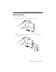
ControlNet Modular Repeater Medium Distance Fiber Module 5 Mount the Fiber Module To mount the module on the DIN rail: 1. Position the module on a 35 x 7.5mm DIN rail at a 30o angle. 2. Hook the lip on the rear of the module onto the top of the DIN rail, and rotate the module onto the rail.
ControlNet Modular Repeater Medium Distance Fiber Module 3. Press the module down onto the DIN rail until flush. The locking tab should snap into position and lock the module to the DIN rail. 4. If the module does not snap into position, use a screwdriver or similar device to move the locking tab down while pressing the module flush onto the DIN rail. Release the locking tab to lock the module in place. If necessary, push up on the locking tab to lock.
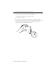
ControlNet Modular Repeater Medium Distance Fiber Module 7 5. Remove the protective backplane cap as shown in “Remove the Protective Caps” on page 8. 6. Once attached to the DIN rail, slide modules to the left to mate with the repeater adapter or another repeater module. 30043-M ATTENTION ! Be certain that the adapter and repeater modules are secured together with DIN rail anchors. Failure to do so may result in the loss of communications and/ or cause damage to the modules.
ControlNet Modular Repeater Medium Distance Fiber Module Remove the Protective Caps 1. Remove the protective caps from the fiber ports that you are going to use. 2. Save the caps for future use. Figure 2 Protective Caps Protective backplane cap DIN rail Protective cap The left side of the module (not shown here) also contains a backplane connector If you plan: Then: to place the module in storage keep the protective caps on the channels to protect the unit from dust.
ControlNet Modular Repeater Medium Distance Fiber Module 9 Choose Fiber Cable Types Multi-fiber cables for backbone use are available with a wide range of fiber counts; between 2 and 216 fibers. The following figure shows an example of a multi-fiber backbone cable and two fiber interconnect cable. The type of fiber cable you choose to use depends on the network environment. Consult your installation professional to determine the best type of cable to use for your environmental conditions.
ControlNet Modular Repeater Medium Distance Fiber Module Specifications for 9904-RPFM Fiber Optic Cable The quality of the fiber cable determines the distance you can achieve. Consult your local distributor for attenuation specifications prior to purchasing your fiber media components. The table below provides specifications for fiber optic cable: Item Description Fiber Type 62.
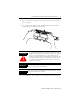
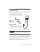
ControlNet Modular Repeater Medium Distance Fiber Module 11 Connect the Fiber Cable If you are going to use only one channel, use either Channel 1 or Channel 2. To connect the cable for Channel 1: 1. Connect to Channel 1 Receive (RX). a. Align the knob of the cable connector with the groove of the module connector, and insert the connector into Channel 1 RX. Figure 3 Connect the Fiber Cable 9904-R PFM 30044-M b. Twist the Receive connector until the bayonet lug is locked into place 2.
ControlNet Modular Repeater Medium Distance Fiber Module Example Topology Figure 4 This topology is for example purposes only. Create a new segment with a fiber repeater. coax segment T T T N N N trunk-cable section coax segment T T FR FR T T T T N N N N trunk-cable section fiber segment 41327 When you insert a fiber repeater into your media system, you create a new segment or link. The same restrictions on the number of taps and cable length apply to this new segment.
ControlNet Modular Repeater Medium Distance Fiber Module IMPORTANT IMPORTANT 13 Be certain that the fiber cable you connect to Channel 1 (RX) on one 9904-RPFM repeater to Channel 1 (TX) on the other 9904-RPFM repeater. You can use Channel 1 or Channel 2 on either module. The total number of fiber repeaters (9904-RPFS, RPFM) between any two nodes (path) is limited to 5 repeaters and 6 segments. You may have many repeaters in a system, but a maximum of five repeaters between any two nodes.
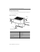
ControlNet Modular Repeater Medium Distance Fiber Module Mounting Dimensions Figure 7 Mounting Dimensions 4.44 in. (111 mm) 2.76 in. (69 mm) 4.0 in. (100 mm) 4.048 in. (101.2 mm) 3.6 in.
ControlNet Modular Repeater Medium Distance Fiber Module 15 Specifications Communication Rate 5M bits/s Operation Voltage Class 2 operational power is provided from 9904-RPA at 5 V dc(2) Backplane Power Requirements 400 mA maximum Indicators Channel 1 Status - Green Channel 2 Status - Green Environmental Conditions This product must be mounted within a suitable system enclosure to prevent personal injury resulting from accessibility to live parts.
Hazardous Location Approval The following information applies when operating this equipment in hazardous locations: Products marked “CL I, DIV 2, GP A, B, C, D” are suitable for use in Class I Division 2 Groups A, B, C, D, Hazardous Locations and nonhazardous locations only. Each product is supplied with markings on the rating nameplate indicating the hazardous location temperature code.