Drive Application Software Function Module Inertia Compensation Imperial Units Reference Manual
FM – Inertia Compensation Important User Information Users of this Reference Manual must be familiar with the application this Function Module is intended to support and its usage. Function Modules intended usage are as a building blocks for a created application. The user must be familiar with the programming tools used to implement this module, the program platform to be used in the application, and the Rockwell Automation drive products to be controlled in the application.
FM – Inertia Compensation Table of Contents 1.0 Precautions ............................................................................................................5 2.0 Definitions ..............................................................................................................6 2.1 Conventions ..........................................................................................................6 2.2 Normalized Quantities.........................................................
FM – Inertia Compensation 4.4.13 4.4.14 4.4.15 4.4.16 4.4.17 4.4.18 5.0 ReverseRotation ................................................................................................................15 J_lbft2................................................................................................................................15 TrqRfJ_Pct.........................................................................................................................15 TrqRfLoss_Pct ....................
FM – Inertia Compensation 1.0 Precautions Class 1 LED Product ATTENTION: Hazard of permanent eye damage exists when using optical transmission equipment. This product emits intense light and invisible radiation. Do not look into module ports or fiber optic cable connectors. General Precautions ATTENTION: This drive contains ESD (Electrostatic Discharge) sensitive parts and assemblies. Static control precautions are required when installing, testing, servicing or repairing this assembly.
FM – Inertia Compensation 2.0 Definitions A Function Module [FM] is a base program designed to perform a specific function (operation) in an application. Function Modules are not complete applications and will require additional programming to control a machine section. The additional programming required for the application and configuration of the overall application is the responsibility of the user.
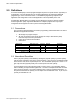
FM – Inertia Compensation 2.3 Terminology 2.3.1 Web A web is defined as the material that is being transported through the machine. A web is sometimes referred to as “sheet” or “strip”. 2.3.2 Strip The strip is defined as the material that is being transported through the machine. A web is sometimes referred to as “sheet” or “web”. The term “strip tension” is referencing the tension of the material in the machine. 2.3.3 Drive The drive is the power device that is transmitting power to the motor.
FM – Inertia Compensation 3.0 Overview The torque applied by the motor, in a web handling application, can be separated into three torque components: 1. Strip Tension Torque 2. Inertia Torque 3. Losses Torque The Inertia Compensation Function Module calculates inertia torque and losses torque. 3.1 Feed Forward Speed regulation, dancer position regulation and strip tension regulation can be improved by feeding inertia and losses torque forward as a torque minor loop reference.
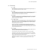
FM – Inertia Compensation 4.0 Functional Description 4.1 Overview The Inertia Compensation Function Module calculates inertia and losses torque using line speed reference as the primary input. The Inertia Compensation Function Module consists of a program with three routines in RSLogix5000: 1. Main (Ladder) 2. JCalc (Ladder) 3. JLossComp (Function Block) The Inertia Compensation Function Module is available in imperial units (English) and international units (SI or metric).
FM – Inertia Compensation If any signal scaling is required to interface the Function Module into the user application, the user may use the main routine for this programming. Note; any scaling for inputs to the routines should be done before the JSR and any scaling applied to the return values from the routines should be done after the JSR. 4.3 JCalc Routine Material width, material density and diameter are used to calculate the roll inertia.
FM – Inertia Compensation 4.3.4 Constant_RPMperFPM This input parameter is the translational-to-rotational conversion constant in RPM/FPM. Usage – From the Diameter Calculator Function Module return parameter of the same name. 4.3.5 Width_in This input parameter is the material width in inches. Usage – Set equal to the material width in inches. 4.3.6 GearRatio This input parameter is the gear ratio expressed as Motor Speed / Roll Speed. Usage – Set equal to the gear ratio. 4.3.
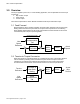
FM – Inertia Compensation 4.4 JLossComp Routine Inertia torque is calculated by multiplying total reflected inertia by angular acceleration: T = J ⋅α where: T is torque J is total inertia α is angular acceleration Angular acceleration is calculated from the rate of change of line speed using the translational-to-rotational conversion constant and build-up ratio (normalized diameter). Separate input parameters are provided for line speed reference and line speed reference rate.
FM – Inertia Compensation The inertia and losses torque return parameter is computed as the sum of inertia torque, friction torque and windage torque. Two conventions are used to avoid confusion when applying signal polarities to translational speed signals, rotational speed signals, and torque signals. 1. Positive torque produces positive rotational speed 2. Positive rotational speed results in positive line speed A reverse rotation input parameter, allows the second convention to be reversed.
FM – Inertia Compensation 4.4.1 LineSpdRf_FPM This input parameter is the line speed reference in FPM. Usage – Set equal to the line speed reference in FPM. 4.4.2 LineSpdRfRate_FPM This input parameter is the rate of change of line speed reference in FPM/second. Usage – If available, set equal to the line speed reference rate, originating in the same routine as LineSpdRf_FPM. 4.4.3 JDiffEnbl This input parameter enables the internal line speed reference differentiator.
FM – Inertia Compensation 4.4.8 JGainQuad1Quad2 This input parameter is the inertia compensation gain for operational quadrants 1 & 2. This parameter is entered as a real number where 1.0 = 100% gain. Quadrant 1 – Positive Speed, Positive Inertia Torque (acceleration forward) Quadrant 2 – Negative Speed, Positive Inertia Torque (deceleration reverse) Usage – Typically set to 1.
FM – Inertia Compensation Usage – Monitor or display only. 4.4.17 TrqRfJLoss_Pct This return parameter is the sum of the inertia and losses torque components in percent of rated motor torque. Usage – Monitor or display only. 4.4.18 DrvTrqRfJLoss_PU This return parameter is the sum of the inertia and losses torque components in perunit rated motor torque with ReverseRotation negate applied.
FM – Inertia Compensation 5.0 Setup / Configuration 5.1 Overview All setup and configuration is done in the Main routine. The Inertia Compensation Function Module is connected to the balance of the application software by placing application tag names in the Jump to Sub-Routine (JSR) instructions. One JSR is used to call the JCalc routine and a second JSR is used to call the JLossComp routine.
FM – Inertia Compensation 5.2.2 Return Parameters 5.2.2.1 Roll Weight and Roll Reflected Inertia Enter application tags, for the Roll Weight and Roll Reflected Inertia return parameter (JCalc - Ret1, Ret2). 5.2.2.2 Total Reflected Inertia [pound-feet2] Enter an application tag, for the Total Reflected Inertia return parameter (JCalc – Ret3). 5.2.2.3 Total Reflected Inertia [Seconds] Enter an application tag, for the Total Reflected Inertia return parameter (JCalc – Ret4).
FM – Inertia Compensation 5.3 JLossComp JSR Instruction 5.3.1 Input Parameters 5.3.1.1 Line Speed Reference Enter an application tag for the Line Speed Reference input parameter (JLossComp – In1). If the application tag value is not in units of FPM, add a rung to the Main routine that will scale the tag value to FPM. 5.3.1.2 Line Speed Reference Rate If available, enter an application tag for the Line Speed Reference Rate input parameter (JLossComp – In2).
FM – Inertia Compensation 5.3.1.13 ReverseRotation Enter an application tag for the ReverseRotation input parameter (JLossComp – In7). For center winder applications, this tag should be derived from the application program overwind and underwind logic. For constant diameter applications, an application tag or an immediate value of 1 can be used. 5.3.2 Return Parameters 5.3.2.
FM – Inertia Compensation 6.0 Tuning / Startup 6.1 Installing the Application Module Perform the following operations in the order listed to ensure proper signal connections between the DriveLogix controller and the PowerFlex 700S firmware. 1. Download the RSLogix 5000 [.acd] file to the DriveLogix controller 2. Download the DriveExecutive [.
FM – Inertia Compensation 6.3 Offline Tuning / Startup Verify that the number and order of JSR input parameters and JSR return parameters agree with the JSR rung comment and section 4 of this user manual. Verify that the data type of all JSR instruction input and return parameters agree with the data type described in the JSR instruction rung comment and section 4 of this user manual.
FM – Inertia Compensation 13. Run the drive with a steady Line Speed Reference that results in a motor speed of just over 2 RPM. 14. Adjust Friction Loss (JLossComp - In11) until the speed PI output is near zero. 15. Run the drive with a steady Line Speed Reference that results in a motor speed near 75% of full speed. 16. Adjust Windage Loss (JLossComp - In12) until the speed PI output is near zero. 17.
FM – Inertia Compensation Appendix A - Process Line Command & Status Words The following table is a functional list of the Process Line command word [wDLx_DrvCmmdProcLn] Bit 00 01 02 03 04 05 06 07 Input Signal Clear Fault Run (2 Wire) Reserved Coast Stop Jog Forward Jog Reverse 08 Stall Tension 09 10 11 12 13 14 15 16 17 18 19 20 21 22 23 24 25 26 27 28 29 Tension Control Torque Control Dancer Control Torque Trim Speed Trim Draw Trim Off Torque Follower Control Diam Preset 1 Diam Preset 2 Diam Preset
FM – Inertia Compensation The following table is a functional list of the Process Line status word [DLx_DrvStatProcLn] Bit 00 01 02 03 04 05 06 07 08 09 10 11 12 13 14 15 16 17 18 19 20 21 22 23 24 25 26 27 28 29 Output Signal Fault Running Reserved Motor Ctrl On Reserved Jogging 30 Operate Permissive 31 On Permissive Rotational Reverse Tension Control On Zero Speed Diameter Calculation Active Reserved Reserved Reserved Reserved Reserved Reserved Enable Loss Fault Fail to Run fault Communication fau
FM – Inertia Compensation Appendix B - Block Diagram NA Drive Application Software – page 26 of 28
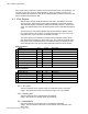
FM – Inertia Compensation Appendix C - Parameter (Tag) Table Input Tags for Inertia Compensation Function Module Name Type Source Tag from Routine Default User Value JCalc – Routine JEC_lbft2 R x.x zDLx_JEC_lbft2 NA 5.0 Density_lbft3 R x.x zDLx_Density_lbft3 NA 43.2 BuildUpRatio R x.x DLx_BuildUpRatio DiamCalc NA Constant_RPMperFPM R x.x DLx_Constant_RPMperFPM DiamCalc NA Width_in R x.x zDLx_Width_in NA 24.0 GearRatio R x.x zDLx_GearRatio NA 5.
Publication: 9329-RM003A-EN-E March 2003 Copyright © 2003 Rockwell Automation. All rights reserved.