
Software Owner's manual


Page | 24
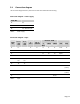
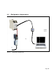
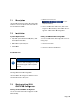
5.4 Connection diagram
Theconnectiondiagrambelowisprintedonthesideofthe931U‐C9C7C‐BChousing.
Connection diagram – Power supply
Term. No.
24 0V
25 PE
26 24‐240VDC/AC
Table4 Powersupply
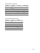
Connection diagram – Input
Term.
No.
I
Passive
<50
mA
I
Active
<20
mA
V
<50 V
TC / V
<600 mV
Resistor / RTD
Poti Freq
2-
Wire
3-Wire 4-Wire
11 In‐ In‐ In‐ R‐ R‐ R‐ Start In‐
12In+Sense‐ Sense‐ End
13 R+ R+ R+ Wiper
14+24V
15 In+/
TP+
I
Return
/
TP+
16 TP‐ TP‐
21In+In+
(<50V)
22 In+
(<30V)
23 Sense+
Table5 Input