Configurator Software Catalog Number 931U-C9C7C-BC User Manual
Page | 2
Foreword Foreword Revision history Version Date 0.0 Change 08/25/2011 First edition Contact address Rockwell Automation 1201 South Second Street Milwaukee, Wisconsin 53204‐2496 USA Phone (1) 414‐382‐2000 Fax (1) 414‐382‐4444 Internet www.ab.
Contents Contents Foreword ............................................................................................................................... 3 Revision history ........................................................................................................................................ 3 Contact address ........................................................................................................................................ 3 Contents.................................
Contents 6.2 931U‐CABLE USB introduction .................................................................................................. 27 6.3 Configuration / diagram wiring ................................................................................................. 28 7. 931U-C9C7C-BC Configurator Software ............................................................. 29 7.1 Description .........................................................................................................
Contents 1. Approvals 1.1 CE ............................................................................................................................................... 7 1.2 UL ............................................................................................................................................... 7 1.3 ATEX ........................................................................................................................................... 7 1.
1.1 CE CE Declaration is available from Rockwell Automation. 1.2 UL Listing approval cULus 1.3 ATEX Approval according ATEX directive EN 60079‐0 and EN 60079‐15 for NON Sparking 1.
2. Notes on Safety 2.1 Electrical precautions ................................................................................................................. 9 2.2 Handling .....................................................................................................................................
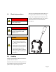
2.1 Electrical precautions There are no procedures which involve the user re‐ moving the product electronics from its housing. Set‐up or Re‐configuration (see chapter 6) is via a connector located behind the front cover, which is opened with the use of a small screwdriver (see Figure 1).
3. Introduction 3.1 Symbol identification................................................................................................................ 11 3.2 Types / article numbers ............................................................................................................ 11 3.3 General description / applications / examples ..........................................................................
3.1 Symbol identification DANGER! Potentially lethal voltages. The CE mark proves the compliance of the product with the requirements of the directives. 3.2 Types / article numbers This User Manual covers the following products: 931U‐C9C7C‐BC Signal Conditioner 931U‐CABLE Programming Cable 3.3 General description / applications / examples The 931U‐C9C7C‐BC is an accurate and stable signal converter / isolator / alarm generator for use in measurement and control systems.
Typical Applications Typical of applications for the 931U‐C9C7C‐BC is the conversion of thermocouple temperature input (low range of millivolts) into a high level (e.g. 4‐20 mA) value for transmission to a control system. In this type of installation the 931U‐C9C7C‐BC pro‐ vides: • Linearization of the standard thermocouple temperature/millivolts characteristic. • Isolation of the input signal to the control sys‐ tem.
ϑ V, I V, V I PS Figure 2 Installation n overview Page | 13 3
4. Operation 4.1 Status & alarm LEDs .................................................................................................................. 15 4.2 Functional block diagram .......................................................................................................... 17 4.3 Specifications ...........................................................................................................................
4.1 S Status & alarm a LE EDs Inp put short circcuit fllashes at 5 Hz H Status LED Cold Junction error e 2 pulses, rests, 2 pulses Under norm mal condition ns this (green n) LED is on con‐ c tinuously. Flash memory error e 3 pulses, rests, 3 pulses Tablle 1 Stattus Indicatorrs A B C Figure 3 LEDs A Status LE ED B ALARM 2 C ALARM 1 The followin ng table show ws how alarm m conditionss are displayed.
Analog Output status with alarm • User may select output value under fault condi‐ tions • Output compliant with NAMUR recommenda‐ tions (NE43) can be set (< 3.6 mA or > 21 mA) Input fault detection Input faults such as short circuit or open circuit can be detected for most input types. These are shown in the table below.
4.
4.3 Specifications Input types Thermocouple Range ‐200...+1820 °C Types B, E, J, K , L, N, R, S, T to IEC 60584 plus custom specific RTD 2, 3, 4 wire, within the range ‐200...+850 °C, for Pt100, Pt1000 to IEC 60571 and for Ni100 / Ni1000 to DIN 43760, for Cu10 and,100 plus custom specific Potentiometer 10 Ω...100 kΩ Resistance 10 Ω...5 kΩ Frequency 2 Hz...100 kHz Voltage within the range ‐200...600 mV (min span 4 mV), within the range ‐20...50 V DC (min span 0.
Min. / max. power supply (according VDE) 18…264 V AC/DC 18…40 V AC / 18…56 V DC (ATEX Zone 2) Rated power < 3,5 W Ambient operating range ‐40...+70 °C Isolation test 1,5 kVrms / 1 min.
5. Installation 5.1 General (Competence Warning) ................................................................................................ 21 5.2 Mounting / Environmental / EMI protection / warm up............................................................ 21 5.3 Electrical Connections ............................................................................................................... 22 5.4 Connection diagram ......................................................................
5.1 General (Competence Warning) The 931U‐C9C7C‐BC should only be installed by technically qualified personnel with sufficient quali‐ fication or knowledge in the subject of instrumenta‐ tion and control engineering. 5.2 Mounting / Environmental / EMI protection / warm up Mounting 931U‐C9C7C‐BC is designed to be mounted onto a TS35 DIN rail. It clips onto the rail via a spring‐loaded mounting foot, and can be removed via a spring release on the edge of the product near the mounting rail.
When auxiliary power is switched on, for the first 200 ms the 931U‐C9C7C‐BC will consume up to 200 mA. 5.3 Electrical Connections Input, output and power supply wiring is made via numbered, pluggable connectors, which may be screw clamp or tension clamp type, depending on the item article number. The connectors are coded to prevent the power supply connector being fitted in the wrong position.
Page | 23
5.4 Connection diagram The connection diagram below is printed on the side of the 931U‐C9C7C‐BC housing. Connection diagram – Power supply Term. No. 24 0V 25 PE 26 24 ‐ 240 V DC / AC Table 4 Power supply Connection diagram – Input Term. No.
Connection diagram – Analog output Term. No. 0…20 mA 31 TP+ 32 Out+ / TP‐ 33 Out‐ 0…10 V 41 Out‐ 42 Out+ 43 Out‐ Table 6 -10 V…+10 V Out+ Analog output Connection diagram – Digital output relay Term. No.
6. Setup / Configuration 6.1 Default setting .......................................................................................................................... 27 6.2 931U‐CABLE USB introduction .................................................................................................. 27 6.3 Configuration / diagram wiring .................................................................................................
6.1 Default setting Input range 4‐20 mA ADS Speed medium Transfer function Linear Response time 0.25 s Output range 4‐20 mA Action direct Low limit 0 mA High Limit 20 mA Output @ error 21.5 mA Digital outputs 1 and 2 Disabled Table 8 6.2 931U-CABLE USB introduction The 931U‐CABLE is the configuration interface for the 931U‐C9C7C‐BC. This is the same interface as can be used for configuring the 931U‐C9A2C‐OP Signal conditioner.
6.
7. 931U-C9C7C-BC Configurator Software 7.1 Description ............................................................................................................................... 30 7.2 Installation ............................................................................................................................... 30 7.3 Starting/exiting 931U‐C9C7C‐BC Configurator ........................................................................... 30 7.4 Title bar ............................
7.1 D Descriptio on The Window ws based 931U‐C9C7C‐BC C Configurattor software is used to set up u the 931U‐C9C7C‐BC via v the interfacce 931U‐CAB BLE. 7.2 1 D Double‐click on the icon on your ccomputer desktop.
7.4 T Title bar File New Chan nge the setting to defaultt settings. Open n a configuraation file *.ttta Open from m the hard disk. Save Savee the actuallyy configuratio on to a file *.tta. Print Printt the actuallyy configuration. Exit Exit the t softwaree 931U‐C9C7 7C‐ BC Configurator. C Figure 7 Setttings Tem mperature un nit Set the unit of the tem mperature for the co onfiguration..
Info About Figure 11 Open n an informaation window w abou ut the softwaare version and a the contact c addrress of Allen‐‐ Brad dley Title bar ‐ Info Page | 32 2
7.5 Overview parameters Input parameters Type of input Voltage ‐ Range V: ‐20 … +50 V DC Min. Span 0.5 V mV: ‐200 … +500 mV DC Min. Span: 4 mV Current ‐ Range Passive Range mA: ‐20 … +50 mA Min. Span: 1 mA Active Range mA: 0 … +20 mA Min.
Voltage range Pin21: Voltage range Pin22: ‐50 V … +50 V DC ‐30 V … +30 V DC Pin High noise reduction High Level Low noise reduction Low Level Max. voltage range 22 550 mV 140 mV ±30 V 21 7.8 V 1.
Transfer parameters Transfer function Transfer function for the output signal: Function linear SQRT 0,5 X^1.5 X^2 X^2.5 Out = In x 0.01 Out = In2,5 x 0.001 Output in % Output in % Output in % 0 0 0 0 10 32 3 1 0.
Figure 12 1 Transffer functionss Figure 13 1 User‐d defined transsfer function n ADC Speed d Fastt Hig ghest sampling ratte 9.
Response Time Medium 50 ‐ 60 Hz 60 ms Slow 50 ‐ 60 Hz 180 ms Response time is the time between an input step and the output step. ADC speed Respons e time in ms Voltage / Current mV / Therm o Potentiometer / RTD 3-Wire RTD 2-Wire 4-Wire min. 140 60 90 60 max. 1000 1000 1000 1000 min. 250 170 350 180 max. 1070 1000 950 1050 min. 525 460 1020 470 max.
Analog output parameters Type of output Voltage Current Voltage Max. Range: ‐10.1 … +11 V DC Max. Range: 0 mA to 20 mA DC Min. Span: 2.5 V DC Min. Span: 5 mA DC Lowest Value Lowest Value This is the minimum voltage value at the output (related to 0% in‐ put). This is the minimum current value at the output (related to 0% input). Highest Value Highest Value This is the value at the output (re‐ lated to 100% input). This is the maximum current value at the output (related to 100% in‐ put).
Digital ou utput param meters Alarm outp put Function Operating modes Dissabled The alarm is disabled. Low w Type The alarm is sw witched on, iff the input value is lowerr than the seetpoint. Higgh Type The alarm is sw witched on, iff the input value is highe er than the seetpoint. Wiindow The alarm is sw witched on, iff the input value is outsid de the windo ow value: win ndow range = setpoint ± window value e.gg.: setpoint 40%, 4 window w 10% = wind dow value is from 30‐50% %.
ON Deelay Sw witch on delay in secondss In 0.1 second steps s OFF Deelay Sw witch off delaay in secondss In 0.1 second steps s Windo ow Sett a range aro ound the Setpoint in perccent Error Action A Alaarm ON The alarm relayy is activated d when an errror is detectted. Alaarm OFF The alarm relayy is deactivated when an n error is detected. Ho old The alarm relayy hold the acctually statuss. No one No o reaction on n an error.
Window A Alarm Figure 16 Window Allarm Page | 41
Alarm Tim me Delay Figure 17 Alarm Timee Delay mple the timee delay is sett for 20 seconds. At t1 thee measurement exceeds the alarm value, but In this exam this only lassts for 10 secconds so there is no trip. At t2 the meeasurement again exceed ds the alarm trip value and this lastts for longer than 20 seconds so the alarm trip occcurs after 20 seconds.
7.6 Run mode Start communication with the 931U‐C9C7C‐BC 1 Connect the 931U‐C9C7C‐BC to a Power supply. 2 Connect the 931U‐C9C7C‐BC with the 931U‐ CABLE to an available USB port on the PC. 3 Start the 931U‐C9C7C‐BC Configurator Software. 4 Input configuration Select the input value. 5 Output configuration Select the output value. 6 Alarm configuration Set the alarm relay behaviour. 7 Send configuration to 931U‐C9C7C‐BC.
• Alarm2: Shows the status of the second alarm relay Table 10 Product identification - LED = red = relay switched on (alarm) - LED = off = relay switched off (no alarm) 7.7 Product identification Unit Type: Description of the module Serial No.: The serial number is printed on the side of the module. Firmware No.: The firmware number of the 931U‐C9C7C‐BC which is connected. Configured by: The company name of the person who last config‐ ured the module.
A Figure 18 Unit‐ID A Terminals Page | 45 5
8. Troubleshooting 8.1 Troubleshooting .......................................................................................................................
8.1 T Troublesh hooting If a 931U‐C9 9C7C‐BC is not working as a expected, the best view of its complette set‐up is via v the 931U‐‐ C9C7C‐BC C Configurator Software. Below are some s examples of checkss which can help h the user oveercome conn nection or co onfiguration er‐ rors. D indication No Status LED C‐BC is installed, the wiring is done, The 931U‐C9C7C on. but it shows no LED indicatio 1 C Check the po ower supply and a considerr the wiring d diagrams and d description ns in chapter 4 and 5.
The green Status LED is flashing It indicates sensor wiring (short circuit or open cir‐ cuit) or internal fault. See description in chapter 3 to identify fault source. 17H The DC output is incorrect 1 Ensure the input type and range are configured as required and wiring connections are correct. 2 Check the output configuration settings for cor‐ rect range and transfer functions including direct or re‐verse action.
Appendix Index ……………………………………………………………………………………………………………….
Index Figure Page Figure 1 Handling 9 Figure 2 Installation overview 13 Figure 3 LEDs 15 Figure 4 Functional block diagram 17 Figure 5 Mounting on DIN rail 21 Figure 7 Configuration / diagram wiring 28 Figure 8 Title bar ‐ File 31 Figure 9 Title bar ‐ Language 31 Figure 10 Title bar ‐ Settings ‐ Temperature unit 31 Figure 11 Title bar ‐ Settings ‐ Set point unit 31 Figure 12 Title bar ‐ Info 32 Figure 13 Transfer functions 36 Figure 14 User‐defined transfer function
Table Page Table 1 Status Indicators 15 Table 2 Input fault detection 16 Table 3 Specifications 19 Table 4 Power supply 24 Table 5 Input 24 Table 6 Analog output 25 Table 7 Digital output 25 Table 8 Default settings 27 Table 9 Parameter 40 Table 10 Product identification 44 Table 11 Article overview Error! Bookmark not defined.
Rockwell Automation 1201 South Second Street Milwaukee, Wisconsin 53204‐2496 USA Phone Fax Internet (1) 414‐382‐2000 (1) 414‐382‐4444 www.ab.
Allen-Bradley and Rockwell Software are trademarks of Rockwell Automation, Inc. Publication 931-UM001A-EN-P -August 2011 - DIR 10000203490 (Version 00) Copyright ©2011 Rockwell Automation, Inc. All Rights Reserved. Printed in USA.