Temperature Controller Communications Functions USER MANUAL Bulletin No.
-ii Important User Information Solid state equipment has operational characteristics differing from those of electromechanical equipment. "Safety Guidelines for the Application, Installation and Maintenance of Solid State Controls” (Publication SGI-1.1 available from your local Rockwell Automation Sales Office or online at http://www.ab.com/ manuals/gi) describes some important differences between solid state equipment and hard-wired electromechanical devices.
-iii European Communities (EC) Directive Compliance If this product has the CE mark it is approved for installation within the European Union and EEA regions. It has been designed and tested to meet the following directives.
-iv Notes: Publication 900-UM004D-EN-E - July 2010
Table of Contents Important User Information . . . . . . . . . . . . . . . . . . . . . . . . . . . . . . . . . -ii European Communities (EC) Directive Compliance. . . . . . . . . . . . . -iii EMC Directive. . . . . . . . . . . . . . . . . . . . . . . . . . . . . . . . . . . . . . . . -iii Low Voltage Directive. . . . . . . . . . . . . . . . . . . . . . . . . . . . . . . . . . -iii Table of Contents Preface Safety Precautions . . . . . . . . . . . . . . . . . . . . . . . . . . . . . . . . . . . . . . . .
-ii Table of Contents Read from Variable Area . . . . . . . . . . . . . . . . . . . . . . . . . . . . . . . . 2-8 Write to Variable Area . . . . . . . . . . . . . . . . . . . . . . . . . . . . . . . . . 2-10 Composite Read from Variable Area . . . . . . . . . . . . . . . . . . . . . 2-12 Composite Write to Variable Area . . . . . . . . . . . . . . . . . . . . . . . 2-13 Read Controller Attributes . . . . . . . . . . . . . . . . . . . . . . . . . . . . . 2-15 Read Controller Status. . . . . . . . . . . . .
Preface Safety Precautions Safety Signal Words This manual uses the following signal word to mark safety precautions for the Bulletin 900-TCx. These precautions provide important information for the safe application of the Bulletin 900-TCx Temperature Controller. You must make sure to follow the instructions provided in all safety precautions.
P-2 Preface How to Read Display Symbols The following table shows the relationship between the symbols exhibited on the controller’s front panel displays to alphabet characters.
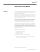
Chapter 1 About Communications Methods Introduction This chapter briefly describes the supported communications methods and how to wire equipment. First-time users must read this chapter to ensure proper installation of the equipment. The programs for the communications functions are created on the host device (PLC or computer), and the 900-TCx's parameters are monitored or set from the host PLC or computer. Therefore, the description provided here is from the viewpoint of the host device.
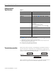
1-2 About Communications Methods Communications Specifications Table 1.
About Communications Methods Interface Communications with the host device are carried out through a standard RS-485 or RS-232C(900-TC8x) interface. Use a cat. no. 900-CONVxx interface converter for RS232C/USB to RS485 conversion. Wiring RS-485 1-3 • RS-485 connections can be 1:1 or 1: N. A maximum of 32 Units (including the host device) can be connected in one-to-N systems. • The total cable length is 500 m max. • Use a shielded, twisted-pair cable #24 AWG (0.205 mm2)…#14 AWG (2.
1-4 About Communications Methods RS-232C (Applies to the 900-TC8 only) • RS-232C connections are 1:1. • The total cable length is 15m max. • Use a shielded, AWG24 to AWG14 (cross-sectional area of 0.205 to 2.081 mm2) twisted-pair cable for the 900-TC8 and 900-TC16. • Use a shielded, AWG24 to AWG18 (cross-sectional area of 0.205 to 0.823 mm2) twisted-pair cable for the 900-TC32. Cable Reference Diagram 900-TCxx #24 AWG…#14 AWG Conductor cross-section 0.205 mm2 to 2.
About Communications Methods Communications parameters 1-5 The 900-TCx's communications specifications are set/configured in the Communications Setting function group. These parameters are set on the 900-TCx's front panel. The table below shows the communications parameters and their ranges. Table 1.
1-6 About Communications Methods Communications Parameter Setup Before you carry out communications with the 900-TCx, set up communications unit number, baud rate and other parameters by carrying out the following procedure. For details of operations other than communications parameter setup, refer to the applicable 900-TCx User Manual. Table 1.
About Communications Methods Communication Parameters 1-7 Note that communications parameters are enabled after they have been changed by resetting the controller. • Protocol Selection (psel) The communications protocol can be selected. Set CompoWay/F (900-TC) or Modbus. • Communications unit number (u-no ) This parameter is for setting a unique unit number for each of the temperature controllers in the system.
1-8 About Communications Methods Setting Communications Writing Set the communications writing parameter to ON to allow the host to write to the 900-TCx controller(s) via communications. Parameter Setting 1. Press the key for less than one second to move from the operation level tot he adjustment level. 2. Select the parameters as shown below by pressing the M key. 3. Use the D or U keys to set the communications writing parameter to ON. c l.
Chapter 2 Bulletin 900 Communications Procedures 900-TCx (CompoWay/F) Data Format Unless otherwise indicated, numbers in this manual are expressed in hexadecimal (with an H’ before the number: e.g., H’02). Values without the H’, such as 00, are ASCII. The number underneath each delimiter in a frame indicates the number of bytes. Command Frame Text Node No. STX 1 2 Sub-address 0 0 2 SID 0 Command Text BCC ETX 1 1 BCC Calculation Range 1 Table 2.
2-2 Bulletin 900 Communications Procedures 900-TCx (CompoWay/F) Response Frame Node No. Sub-address End Code Command Text STX BCC ETX 2 1 2 2 1 1 Table 2.2 End Code Name Description Error Detection Priority 00 Normal completion The command ended normally without error. None 0F FINS command error The specified FINS command could not be executed. The FINS response code should indicate why the command could not be executed.
Bulletin 900 Communications Procedures 900-TCx (CompoWay/F) 2-3 Communications Data Table 2.3 Communications Data Communications Set (Monitor) Specifications Value Minus Value Decimal Point CompoWay/F (Bulletin 900-TCx) 2's complement Decimal point is removed and the result is converted to hexadecimal. Example: 105.0 Æ 1050 Æ H’000041A 8 digits (Hex) Example of End Code The following examples show an end code when a command did not end normally.
2-4 Bulletin 900 Communications Procedures 900-TCx (CompoWay/F) Example 3: No node number provided Command Format: BCC STX ETX The node number is lacking one character. Response Format: No response Example 4: No sub-address, and illegal BCC Command Format: Node No. STX BCC ETX Err Response Format: Node No. STX Sub-address 0 0 End Code 1 Sub-address is 00 and end code is 13 (BCC error).
Bulletin 900 Communications Procedures 900-TCx (CompoWay/F) 2-5 Structure of Command Text PDU (Protocol Data Unit) Structure An MRC (Main Request Code) and SRC (Sub-Request Code) followed by the various required data is transferred to the command text. Service request PDU MRC SRC Data The MRES (Main Response Code) and SRES (Sub-Response Code) are transferred to the response frame following the above MRC/SRC. Data is then transferred following the MRES and SRES.
2-6 Bulletin 900 Communications Procedures 900-TCx (CompoWay/F) Type Code (Variable Type) The following defines variable area type codes. Variable type (1 byte) MSB LSB 0 0 0 Access size 0 Area Read/Write 11: Double-word 0: Setup area 0 0: Read only 10: Word 1 : Setup area 1 1 : Read/write The following table summarizes setup areas 0 and 1. Table 2.4 Area Description Setup area 0 This area groups together the Protect, Manual Control, Operation and Adjustment function groups.
Bulletin 900 Communications Procedures 900-TCx (CompoWay/F) 2-7 Number of Elements The number of elements is expressed in 2-byte hexadecimal code. The range that can be specified for the number of elements depends on the command. Refer to Detailed Description of Services on page 2-8. List of Services Table 2.6 MRC SRC Name of Service Process 01 01 Read from variable area This service reads from variable areas. 01 02 Write to variable area This service writes to variable areas.
2-8 Bulletin 900 Communications Procedures 900-TCx (CompoWay/F) Detailed Description of Services Read from Variable Area This service reads from variable areas.
Bulletin 900 Communications Procedures 900-TCx (CompoWay/F) 2-9 Response code Normal Completion Table 2.8 Response Code Name Description 0000 Normal completion No errors were found. Error Occurred Table 2.9 Response Code Error Name Cause 1001 Command too long The command is too long. 1002 Command too short The command is too short. 1101 Area type error The variable type is wrong. 1103 Start address out-of-range error The read start address is out of range.
2-10 Bulletin 900 Communications Procedures 900-TCx (CompoWay/F) Write to Variable Area This service writes to the controller’s variable areas.
Bulletin 900 Communications Procedures 900-TCx (CompoWay/F) 2-11 Response code Normal Completion Table 2.11 Response Code Name Description 0000 Normal completion No errors were found. Error Occurred Table 2.12 Response Code Error name Cause 1002 Command too short The command is too short. 1101 Area type error Wrong variable type 1103 Start address out-of-range error Write start address is out of range.
2-12 Bulletin 900 Communications Procedures 900-TCx (CompoWay/F) Composite Read from Variable Area This service reads in order the contents of specified addresses in the variable area.
Bulletin 900 Communications Procedures 900-TCx (CompoWay/F) 2-13 Table 2.14 Response Code Name Description 0000 Normal Completion No errors were found. Response Code Name Description 1002 Command too short The command is too short. 1101 Area type error The variable type is wrong. 110B Response too long The number of elements exceeds the maximum. 1100 Parameter error Bit position is not “00”. 2203 Operation error EEPROM error. Error occurred Table 2.
2-14 Bulletin 900 Communications Procedures 900-TCx (CompoWay/F) Number of Write Data Items (Variable Type + Write Data) Table 2.16 Read Data Length Number of Read Data Items For double word 12 max. For word 17 max. Response Code Normal completion Table 2.17 Response Code Name Description 0000 Normal Completion No errors were found. Response Code Name Description 1002 Command too short The command is too short. 1101 Area type error The variable type is wrong.
Bulletin 900 Communications Procedures 900-TCx (CompoWay/F) 2-15 Read Controller Attributes This service reads the model number and communications buffer size. Service Request PDU MRC SRC 0 5 0 3 2 2 Service Response PDU MRC SRC 0 5 0 3 2 2 Response code Model No. 4 10 Buffer size 0 0 D 9 4 Model Number The model number is expressed in 10-byte ASCII. When 10 bytes are not required, pad the remaining bytes with spaces.
2-16 Bulletin 900 Communications Procedures 900-TCx (CompoWay/F) Read Controller Status This service reads the operating and error status of the controller.
Bulletin 900 Communications Procedures 900-TCx (CompoWay/F) 2-17 Operating status Table 2.21 Run Status Description 00 Control is being carried out (error has not occurred in setup area 0, and the controller is running). 01 Control is not being carried out (state other than above).
2-18 Bulletin 900 Communications Procedures 900-TCx (CompoWay/F) Service Response PDU MRC SRC 0 0 8 2 Response Code Test Data 1 2 0 to 200 Test data Set any test data within the range 0…200 bytes of user-defined test data. Set a value for the test data within the ranges shown below according to the communications data length. Table 2.24 Communications Data Length Test Data 8 bits ASCII data: H’20 to H’7E, or H’A1 to H’FE 7 bits ASCII data: H’20 to H’7E Do not set H’40.
Bulletin 900 Communications Procedures 900-TCx (CompoWay/F) 2-19 Operation Commands This service performs operations like the following: • • • • • • • • Communications Writing RUN/STOP Multi-SP AT Execute/Cancel Write Mode Save RAM Data Software Reset Move to Setup Area 1 • • • • • Move to Protect Group Auto/Manual Switch Parameter Initialization Alarm Latch Cancel Invert Direct/Reverse Operation • Program Start Service Request PDU MRC SRC 3 0 0 5 2 2 Com- Related mand information code 2 2 Service
2-20 Bulletin 900 Communications Procedures 900-TCx (CompoWay/F) Command Code and related information Table 2.
Bulletin 900 Communications Procedures 900-TCx (CompoWay/F) 2-21 Error Occurred Table 2.29 Response Code Error name Cause 1001 Command too long The command is too long. 1002 Command too short The command is too short. 1100 Parameter error Instruction code and related information are wrong. 2203 Operation error • The Communications Writing parameter is set to OFF (disabled). However, note that the error is accepted regardless of the Communications Writing parameter setting (ON/OFF).
2-22 Bulletin 900 Communications Procedures 900-TCx (CompoWay/F) area 0 and setup area 1. An operation error will occur in the following situations. – When AT is being executed. – When the Multi-SP Uses parameter is set to OFF. – When the Multi-SP Uses parameter is set to ON but multi-SP is set for an event input (Number of Multi-SP Uses > 0). • AT Execute/Cancel Set AT (auto-tuning) to “execute” or “cancel” with the related information setting. This command can be accepted in setup area 0 only.
Bulletin 900 Communications Procedures 900-TCx (CompoWay/F) 2-23 – When the mode is switched from RAM write mode to backup mode, the parameters in the Operation/Adjustment groups (excluding read-only parameters) are written to EEPROM. – The RAM write mode is enabled only when the Communications Writing parameter is set to “ON” (enabled).
2-24 Bulletin 900 Communications Procedures 900-TCx (CompoWay/F) mode while already in manual mode, the command will be completed normally and the display will not change (the contents will not be refreshed). • Writing Auto/Manual Status in EEPROM The write mode determines whether the auto/manual status is written to EEPROM. Table 2.31 Write Mode Description Backup mode When the auto/manual mode is switched by communications, the auto/manual status is written to EEPROM.
Bulletin 900 Communications Procedures 900-TCx (CompoWay/F) 2-25 1. An operation error will occur if communications writing is disabled or if an EEPROM error occurs. • Invert Direct/Reverse Operation Inverting or not inverting direct/reverse operation can be selected with the related information setting. The setting can be accepted in both setup area 0 and setup area 1. The related information specifications are written to EEPROM according to the write mode settings.
2-26 Bulletin 900 Communications Procedures 900-TCx (CompoWay/F) Response Code List Normal Completion Table 2.33 Response Code Name Description Error Detection Priority 0000 Normal completion No errors were found. None Error Occurred Table 2.34 Response Code Name Description Error Detection Priority 0401 Unsupported command The service function for the relevant command is not supported. 1 1001 Command too long The command is too long.
Chapter 3 Communications Data Variable Area (setup range) List This chapter lists the details of each of the communications data in the Bulletin 900-TCx communications procedures. For communications using a variable type not enclosed in parentheses in the following table, the set value is double-word data (8 digits). For communications using a variable type enclosed in parentheses, the set value is single-word data (4 digits).
3-2 Communications Data Table 3.1 Variable Type C0 (80) Variable Type Address Item (Parameter) Name C0 (80) 0000 Process value Set (monitor) Value Function Group Temperature: Follow the specified range of the sensor. Operation Analog: Scaling lower limit -5%FS to scaling upper limit +5%FS C0 (80) 0001 Status➊➋ Refer to Status Structure on page 3-13 C0 (80) 0002 Internal set point➊ SP lower limit to SP upper limit C0 (80) 0003 Heater current 1 value H’00000000…H’00000226 (0.0…55.
Communications Data 3-3 Table 3.
3-4 Communications Data Table 3.2 Variable Type C1 (81) Variable Type Address Item (Parameter) Set (Monitor) Value Function Group C1 (81) 0025 SP ramp set value H’00000000 (0): OFF H’00000001…H’0000270F (1…9999) Adjust ment C1 (81) 0026 MV upper limit Standard: MV lower limit + 0.1…H’0000041A (MV lower limit + 0.1…105.0) Heating and cooling: H’00000000…H’0000041A (0.0…105.0) C1 (81) 0027 MV lower limit Standard: H’FFFFFFCE…MV upper limit − 0.1 (−5.0…MV upper limit − 0.
Communications Data 3-5 Table 3.3 Variable Type C3 (83) Variable Type Address Item (Parameter) Set (Monitor) Value Function Group C3 (83) 0000 Input Type (TC/Pt multi-input models) ➊ H’00000000 (0): Pt (−200…850°C/−300…1500°F) H’00000001 (1): Pt (−199.9…500.0°C/−199.9…900.0°F) H’00000002 (2): Pt (0.0…100.0°C/0.0…210.0°F) H’00000003 (3): JPt (−199.9…500.0°C/−199.9…900.0°F) H’00000004 (4): JPt (0.0…100.0°C/0.0…210.0°F) H’00000005 (5): K (−200…1300°C/−300…2300°F) H’00000006 (6): K (−20.0…500.0°C/0.
3-6 Communications Data Table 3.3 Variable Type C3 (83) Variable Type Address Item (Parameter) Set (Monitor) Value C3 (83) 0009 ST H’00000000(0): H’00000001(1): C3 (83) 000A Control Period (heat) H’00000000 (0): 0.5 H’00000001…H’00000063 (1…99) C3 (83) 000B Control Period (cool) H’00000000 (0): 0.
Communications Data 3-7 Table 3.
3-8 Communications Data Table 3.3 Variable Type C3 (83) Variable Type Address Item (Parameter) Set (Monitor) Value C3 (83) 002B Input digital filter H’00000000…0000270F (0.0…999.
Communications Data 3-9 Table 3.
3-10 Communications Data Table 3.3 Variable Type C3 (83) Variable Type Address Item (Parameter) Set (Monitor) Value Function Group C3 (83) 004E Control output 1 assignment When control output 1 is a linear output: H’00000000 (0): Not assigned. H’00000001 (1): Control output (heating) H’00000002 (2): Control output (cooling) When control output 1 is an ON/OFF pulse output: H’00000000 (0): Not assigned.
Communications Data 3-11 Table 3.
3-12 Communications Data Table 3.3 Variable Type C3 (83) Variable Type Address Item (Parameter) Set (Monitor) Value Function Group C3 (83) 0071 Monitor/Setting Item 4 H’00000000...H’0000000F (0 ...5) * Same as for Monitor/Setting Item 1. C3 (83) 0072 Monitor/Setting Item 5 H’00000000...H’0000000F (0 ...5) * Same as for Monitor/Setting Item 1.
Communications Data Status Structure 3-13 Figure 3.
3-14 Communications Data Figure 3.2 Status Structure Data (Continued) HB Error | Operating Status | Event Inputs 31 30 29 28 27 26 25 24 23 22 21 20 19 18 17 16 15 0 0 Bit position 0 Event input 1 Event input 2 Write mode EEPROM Setup area AT execute/cancel Run/Stop Communications writing Auto/manual switch Program Start Heater overcurrent (CT2) Heater current hold (CT2) HS alarm output (CT2) Figure 3.
Communications Data 3-15 The table below shows the status details. Table 3.
3-16 Communications Data Table 3.
Chapter 4 Modbus Communications Procedure Read this section if you are to communicate using the Modbus format. Data Format The data format complies with the Modbus (RTU) communications protocol, so commands from the host computer and responses from the 900-TC8, 900-TC16, or 900-TC32 are contained in data blocks called frames. The structure of the command and response frames is described below. In the following explanations, hexadecimal values are expressed by adding the prefix H’ before the number, e.
4-2 Modbus Communications Procedure Table 4.1 Silent interval of 3.5 character times min. Slave address Specify the unit number. The unit number can be set between H’00 to H’63 hexadecimal (0…99 decimal). Specify H’00 for a broadcast transmission. No responses will be returned for broadcast transmissions. Function code The function code is a 1-byte hexadecimal code that indicates the type of command sent from the host device. Data This is the text data associated with the specified function code.
Modbus Communications Procedure 4-3 Example of Appending the Calculation Result When the calculated CRC value is H’1234, the CRC value is appended to the command frame as shown in Figure 4.2. Figure 4.2 Slave Function address code 1 Data 1 CRC-16 Low High H'34 H'12 2 bytes CRC-16 calculation range Response Frame Normal Response Frame Figure 4.3 Slave Function address code 1 Data 1 CRC-16 2 bytes CRC-16 calculation range Error Response Frame Figure 4.
4-4 Modbus Communications Procedure Table 4.2 Slave address The number specified in the command frame is entered as-is. This is the unit number of the Unit returning the response. Function code This is the received function code with the hexadecimal value of 80 added to indicate that the response is an error response. Example: Received function code = H’03 Function code in response frame when an error occurred = H’83 Error code This code indicates the kind of error that occurred.
Modbus Communications Procedure 4-5 No Response In the following cases, the received command will not be processed and a response will not be returned. Consequently, a timeout error will occur at the host device. · The slave address in the received command does not match the communications unit number. · A parity error, framing error, or overrun error occurred due to a problem such as a transfer error. · A CRC-16 code error occurred in the received command frame.
4-6 Modbus Communications Procedure The variable area is the region of memory used to exchange data with the 900-TC8, 900-TC16, or 900-TC32 through communications. Variable Area Operations such as reading the process value and Reading/Writing parameters are performed on the variable area. On the other hand, operation commands do not use the variable area. Figure 4.5 900-TC8 or 900-TC16 Operation commands, etc.
Modbus Communications Procedure 4-7 Modbus Addresses Corresponding to 900-TC (CompoWay/F) Setup Areas 0 and 1 Setup Area 0 and Setup Area 1 do not correspond directly to Modbus addresses, but the following areas have a rough correspondence with one exception. Table 4.
4-8 Modbus Communications Procedure Example: D’105.0 → H’0000041A The variables are 4- or 8-digit hexadecimal values. Negative values are expressed in 2’s complement format. The values are hexadecimal values with no decimal point indication. For example, if the 900-TC8 , 900-TC16, or 900-TC32’s process value is read in 4-byte mode when the process value is 105.0, the read value will be H'0000041A (105.0 → 1050 → H'0000041A).
Modbus Communications Procedure 4-9 Table 4.6 Name Description Slave address Specify the 900-TCx’s unit number. The unit number can be set between H’01 and H’63 hexadecimal (1…99 decimal). Function code The Read Variable Area function’s function code is H’03. Read start address Specify the address containing the data to be read. Refer to Chapter 5 Communications Data for Modbus for details on addresses.
4-10 Modbus Communications Procedure Figure 4.8 Response Frame Slave Function Byte address code count Read data (for the number of elements) CRC-16 0 to 212 (2 × 10⁶) 2 H'03 1 1 1 Table 4.7 Name Description Slave address The value from the command frame is entered as-is. Function code This is the received function code. When the function ended normally, the function code is left as-is.
Modbus Communications Procedure 4-11 Reading Undisplayed Parameters It is possible to read the parameters that are not displayed due to display settings as well as the parameters that are never displayed in the Controller. Example Command and Response The following example shows the command/response when reading the process value. (In this case, the slave address is H’01.) Process Value in 4-Byte Mode Address: H’0000; Read data: H’000003E8 (100.0 °C) Figure 4.9 Figure 4.
4-12 Modbus Communications Procedure Table 4.9 Name Description Slave address Specify the 900-TC8, 900-TC16, or 900-TC32’s unit number. The unit number can be set between H’01 and H’63 hexadecimal (1…99 decimal). Function code The Write Variable Area function’s function code is H’10. Write start address Specify the starting address where the setting data will be written. Refer to Chapter 5 Communications Data for Modbus for details on addresses.
Modbus Communications Procedure 4-13 Table 4.10 Name Description Slave address The value from the command frame is entered as-is. Function code This is the received function code. When the function ended normally, the function code is left as-is. When an error occurred, the hexadecimal value of H’80 is added to the function code to indicate that the response is an error response.
4-14 Modbus Communications Procedure Example Command and Response The following example shows the command/response when writing the Upper-Limit Alarm 1 and Lower-Limit Alarm 1 parameters. (In this case, the slave address is H’01.) • Four-Byte Mode Upper-Limit Alarm 1 · Address: H’010A Write data: H’000003E8 (when 1,000) Lower-Limit Alarm 1 · Address: H’010C Write data: H’FFFFFC18 (when −1,000) Figure 4.
Modbus Communications Procedure 4-15 Variable Write, Single/Operation Command This function performs operations such as writing to the variable area (single) and operation commands (communications writing, RUN/STOP, multi-SP, AT execute/cancel, write mode, save RAM data, software reset, move to setup area 1, move to protect level, auto/manual switch, initialize settings, alarm latch cancel, invert direct/reverse operation, and program start.) Writing is enabled in only the 2-byte mode. Figure 4.
4-16 Modbus Communications Procedure Command Code and Related Information Table 4.
Modbus Communications Procedure 4-17 Error Occurred Table 4.14 Function code Error code Name Description H’86 H’02 Variable address error • The write variable address is incorrect. • The variable area number (2-byte data) is wrong, or the address is not 0000 or FFFF. H’03 Variable data error The write data is incorrect. • The write data is out of the setting range.
4-18 Modbus Communications Procedure Operation Commands and Precautions • Communications Writing Set the Communications Writing parameter to “ON” (enabled) or “OFF” (disabled) with the related information setting. The setting can be accepted in both setup area 0 and setup area 1. An operation error will occur, however, if communications writing enable/disable is set for an event input. • RUN/STOP Set control to “run” or “stop” with the related information setting.
Modbus Communications Procedure 4-19 Table 4.15 Write Mode Description Backup mode The data is written to EEPROM when the parameters in the Operation/Adjustment function groups (excluding read-only parameters) are written by communications. RAM write mode The data is not written to EEPROM when the parameters in the Operation/Adjustment function groups (excluding read-only parameters) are written by communications. Parameters can be changed by operating the keys on the front panel of the controller.
4-20 Modbus Communications Procedure · Moving the Protect function group in Manual Mode When this operation command is issued in manual mode, an Operation Error will be generated, and the move to the Protect function group will be prohibited. · Auto/Manual Switch This operation command switches the mode to manual mode or automatic mode, based on the related information setting. This command can be accepted in Setup Area 0 only.
Modbus Communications Procedure 4-21 · Switching to Manual Mode during Auto-Tuning If the mode is switched during Auto-Tuning (AT), the AT will be cancelled and the Controller will be switched to manual mode. · Parameter Initialization The present settings are returned to the default values and written to EEPROM. This command can be accepted in Setup Area 1 only. When this command is issued in Setup Area 0, an Operation Error will be generated.
4-22 Modbus Communications Procedure Table 4.17 Related Information Explanation (Initialization Values) 00 Default set values (refer to Chapter 2, Bulletin 900 Communications Procedures 900-TCx (CompoWay/F) for details.) (These settings are the same as the ones used when “FACT” is selected for the setting data’s set value initialization.) • Alarm Latch Cancel The applicable alarm latch can be cleared with the related information setting.
Modbus Communications Procedure 4-23 Power ON Software reset command Setting area 0 “Move-to-setting area 1” command Control in progress Setting area 1 Control stopped. Echoback Test Figure 4.18 Command Frame Slave Function Write address code start address H'08 1 H'00 1 Test data CRC-16 H'00 2 2 2 bytes Figure 4.
4-24 Modbus Communications Procedure (In this case, the test data is H’1234 and the slave address is H’01.) Figure 4.
Chapter 5 Communications Data for Modbus This section lists the details of the communications data in the Modbus communications protocol. Variable Area (Setting Range) List • Four-byte Mode One element uses 2 bytes of data (H'0000 to H'FFFF), so specify two element units. Reading and writing in 4-byte units is executed by specifying an even address and specifying the number of elements in multiples of 2. • Two-byte Mode One element uses 2 bytes of data (H'0000 to H'FFFF), so specify one element units.
5-2 Communications Data for Modbus Table 5.1 Address Parameter Name Setting (Monitor) Value Four-Byte Two-Byte mode mode 0000 2000 PV Temperature: Use the specified range for each sensor. Analog: Scaling lower limit − 5% FS…Scaling upper limit + 5% FS 0002 2001 Status ➊➋ See STATUS AND STATUS 2 for details. 0004 2002 Internal Set Point ➊ SP lower limit…SP upper limit 0006 2003 Heater Current 1 Value Monitor H’00000000…H’00000226 (0.0…55.
Communications Data for Modbus 5-3 Table 5.2 Address Four Byte Model Parameter Name Setting (Monitor) Value Two Byte Model Function Group 0500 2500 Operation/Adjustment Protect H’00000000 (0): No restrictions in Operation and Adjustment function groups Protect H’00000001 (1): Move to Adjustment function group is prohibited. H’00000002 (2): Display and change of only PV and PV/SP parameters is allowed. H’00000003 (3): Display of only PV and PV/SP parameters is allowed.
5-4 Communications Data for Modbus Table 5.3 Address Four-byte mode Parameter Name Setting (Monitor) Value Two-byte mode Function Group 0700 2700 Cooling Coefficient H’00000001…H’0000270F (0.01…99.99) Adjustment 0708 2704 Dead Band H’FFFFF831…H’0000270F (−199.9…999.9 for TC/Pt multi-input models) (−19.99…99.99 for Analog input models) 070A 2705 Manual Reset Value H’00000000…H’000003E8 (0.0…100.0) 070C 2706 Hysteresis (Heating) H’00000001…H’0000270F (0.1…999.
Communications Data for Modbus 5-5 Table 5.4 Address Four-byte mode Parameter Name Setting (Monitor) Value Two-byte mode Function Group 0750 2728 Soak Time Remain Monitor H’00000000…H’0000270F (0…9999) Operating 0752 2729 Soak Time H’00000001…H’0000270F (1…9999) Adjustment 0754 272A Wait Band H’00000000 (0): OFF H’00000001…H’0000270F (0.1…999.9 for TC/Pt multi-input models) (0.01…99.99 for Analog input models) 0756 272B Heater Overcurrent Detection 1 H’00000000…H’000001F4 (0.0…50.
5-6 Communications Data for Modbus Table 5.5 Address Four-byte mode 0C00 Parameter Name Setting (Monitor) Value Two-byte mode 2C00 Input Type (TC/Pt Multi-Input Models) ➊ H'00000000 (0): Pt (-200 to 850°C/-300 to 1500°F) H'00000001 (1): Pt (-199.9 to 500.0°C/-199.9 to 900.0°F) H'00000002 (2): Pt (0.0 to 100.0°C/0.0 to 210.0°F) H'00000003 (3): JPt (-199.9 to 500.0°C/-199.9 to 900.0°F) H'00000004 (4): JPt (0.0 to 100.0°C/0.0 to 210.
Communications Data for Modbus 5-7 Table 5.
5-8 Communications Data for Modbus Table 5.
Communications Data for Modbus 5-9 Table 5.
5-10 Communications Data for Modbus Table 5.9 Address Parameter Name Setting (Monitor) Value Four-byte Two-byte mode mode Function Group 0F0E 2F07 Alarm 3 Latch ➊ H'00000000 (0): OFF H'00000001 (1): ON Advanced Setting 0F10 2F08 Alarm 3 Hysteresis ➊ H'00000001…H'0000270F (0.1…999.9 for TC/Pt multi-input models) (0.01…99.
Communications Data for Modbus 5-11 Table 5.
5-12 Communications Data for Modbus Table 5.
Communications Data for Modbus 5-13 Table 5.
5-14 Communications Data for Modbus Figures 5.1, 5.3 and 5.3 and Tables 5.11 and 5.12 show the structure of the status data. NOTE: Spare bits are always OFF. Status Figure 5.
Communications Data for Modbus 5-15 Figure 5.
5-16 Communications Data for Modbus Table 5.
Communications Data for Modbus Table 5.
5-18 Communications Data for Modbus Notes: Publication 900-UM004D-EN-E - July 2010
Appendix A ASCII Table b8 b8 b7 Even parity A-1 b6 b5 b4 0 0 0 0 0 0 0 0 1 1 1 1 1 1 1 1 b3 0 0 0 0 1 1 1 1 0 0 0 0 1 1 1 1 b2 0 0 1 1 0 0 1 1 0 0 1 1 0 0 1 1 b1 0 1 0 1 0 1 0 1 0 1 0 1 0 1 0 1 b7 0 0 0 0 1 1 1 1 b6 0 0 1 1 0 0 1 1 b5 0 1 0 1 0 1 0 1 0 1 2 3 4 5 6 7 8 9 A B C D E F 0 NUL SOH STX ETX EOT ENQ ACK BEL BS HT LF VT FF CR SO SI 1 DEL DC1 DC2 DCS DC4 NAK SYN ETB CAN EN SUB ESC FS GS RS US 2 SPACE ! n # $ % & / ( ) * + ) - 3 0 1 2 3 4 5 6 7 8 9 4 @ A B C
A-2 Notes: Publication 900-UM004D-EN-E - July 2010
Back Cover Publication 900-UM004D-EN-E - July 2011 1-1 Supersedes Publication 900-TC004C-EN-E - October 2008 © 2011 Rockwell Automation. Printed in the U.S.A.