
User guide

Publication 900-UM007D-EN-E - January 2011
Preparations 2-25
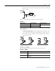
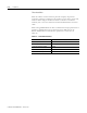
Select a surge absorber that satisfies the following conditions.
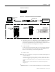
Wiring Auxiliary Outputs (1, 2, and 3)
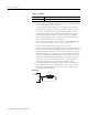
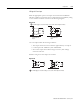
• On the 900-TC8, Auxiliary Output 1 (SUB1) is output across terminals
9 and 10, Auxiliary Output 2 (SUB2) is output across terminals 7 and 8,
and Auxiliary Output 3 (SUB3) is output across terminals 5 and 6.
• When the HBA or the HS Auxiliary is used with the 900-TC8,
Auxiliaries are output across terminals 9 and 10.
• On the 900-TC8, when heating/cooling control is used, Auxiliary
Output 3 becomes control output (cooling).
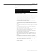
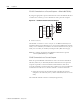
• On the 900-TC16, Auxiliary Output 1 (SUB1) is output across terminals
7 and 8, and Auxiliary Output 2 (SUB2) is output across terminals 6
and 8.
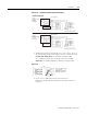
• On the 900-TC32, Auxiliary Output 1 (SUB1) is output across terminals
5 and 6.
• On the 900-TC32, when heating/cooling control is used, auxiliary
output 1 becomes control output (cooling).
• When the HB, the HS, or heater overcurrent alarm is used with the
900-TC16, alarms are output across terminals 7 and 8.
• On the 900-TC16, when heating/cooling control is used, Auxiliary
Output 2 becomes control output (cooling).
• When the Input Error Output parameter is configured to ON, the
output assigned to Alarm Output 1 turns ON when an input error
occurs.
• For models that have a Heater Burnout Alarm (not supported by
900-TC32), an OR of the alarm 1 function and the HB/HS or heater
overcurrent alarm is sent to the output assigned to the alarm 1 function
(auxiliary output 1). If ALM1 is to be used for HBA only, configured the
Alarm 1 type to 0 and do not use Alarm function 1.
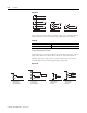
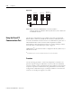
• The following diagrams show the internal equalizing circuits for Alarm
Outputs 1, 2, and 3.
Table 2.J
Voltage Used Varistor Voltage Surge Resistance
100…120V AC 240…270V 1,000 A min.
200…240V AC 440…470V