
User guide


B-1 Publication 900-UM007D-EN-E - January 2011
Appendix
B
Parameter Operations List
Function Groups
Global Temperature input:Controllers with Thermocouple/Resistance
Thermometer (RTD) and Millivolt (0…50) Inputs
Analog input:Controllers with Analog (e.g., 4…20 mA, 1…5V DC, etc.) Inputs
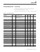
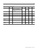
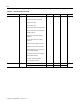
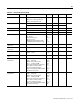
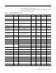
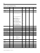
Table B.A — Operation Function Group
Parameters Characters Setting (Monitor) Value Display Default Unit
Set
Value
Process Value Temperature: According to indication
range for each sensor. Analog:
Scaling lower limit
-5% FS to Scaling upper limit+5% FS
EU
Set Point SP Lower-Limit to SP Upper-Limit 0 EU
Auto/Manual Switch a-m
Multi-SP Set Point Setting m-sp 0…3 0 None
Set Point During SP Ramp sp-m SP Lower-Limit to SP Upper-Limit EU
Heater Current 1 Value Monitor ct1 0.0…55.0 A
Heater Current 2 Value Monitor ct2 0.0…55.0 A
Leakage Current 1 Monitor lcr1 0.0…55.0 A
Leakage Current 2 Monitor lcr2 0.0…55.0 A
Program Start prst RSET, STRT rset
strt
RSET None
Soak Time Remain sktr 0…9999 min or h
RUN/STOP r-s RUN/STOP run
stop
RUN None
Alarm Value 1 al-1 −1999…9999 0 EU
Alarm Value Upper-Limit 1 al1h −1999…9999 0 EU
Alarm Value Lower-Limit 1 al1l −1999…9999 0 EU
Alarm Value 2 al-2 −1999…9999 0 EU
Alarm Value Upper-Limit 2 al2h −1999…9999 0 EU
Alarm Value Lower-Limit 2 al2l −1999…9999 0 EU
Alarm Value 3 al-3 −1999…9999 0 EU
Alarm Value Upper-Limit 3 al3h −1999…9999 0 EU
Alarm Value Lower-Limit 3 al3l −1999…9999 0 EU
MV Monitor (heating) o −5.0…105.5 (standard)
0.0…105.0 (heating/cooling)
%
MV Monitor (cooling) c-o 0.0…105.0 %