
User guide

Publication 900-UM007D-EN-E - January 2011
Parameter Functions & Definitions 5-51
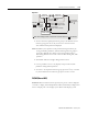
• If a platinum resistance thermometer (RTD) is mistakenly connected
while a setting for other than a platinum resistance thermometer is in
effect, the controller error code S.ERR will be displayed. To clear the
S.ERR display, check the wiring and then cycle the controller power.
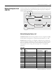
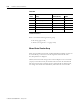
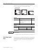
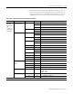
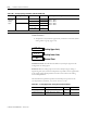
Table 5.BD — Global Temperature (GT) Input Type Controllers
Input Type Specifications Set Value Input Temperature Range
Controller
Type with
Thermocouple
and
Resistance
Thermometer
(RTD) inputs
Platinum resistance
thermometer (RTD)
Pt100 0 −200…850 (°C)/−300…1,500 (°F)
1 −199.9…500.0 (°C)/−199.9…900.0 (°F)
2 0.0…100.0 (°C)/0.0…210.0 (°F)
JPt100 3 −199.9…500.0 (°C)/−199.9…900.0 (°F)
4 0.0…100.0 (°C)/0.0…210.0 (°F)
Thermocouple K
5 −200…1,300 (°C)/−300…2,300 (°F)
6 −20.0…500.0 (°C)/0.0…900.0 (°F)
J7−100…850 (°C)/−100…1,500 (°F)
8 −20.0…400.0 (°C)/0.0…750.0 (°F)
T9−200…400 (°C)/−300…700 (°F)
10 −199.9…400.0 (°C)/−199.9…700.0 (°F)
E 11 -200…600 (°C)/-300…1,100 (°F)
L12−100…850 (°C)/−100…1,500 (°F)
U13−200…400 (°C)/−300…700 (°F)
14 −199.9…400.0 (°C)/−199.9…700.0 (°F)
N15−200…1,300 (°C)/−300…2,300 (°F)
R 16 0…1,700 (°C)/0…3,000 (°F)
S 17 0…1,700 (°C)/0…3,000 (°F)
B 18 100…1,800 (°C)/300…3,200 (°F)
Infrared T
e
mperature
Sensor
ES1B
10…70 (°C) 19 0…90 (°C)/0…190 (°F)
60…120 (°C) 20 0…120 (°C)/0…240 (°F)
115…165 (°C) 21 0…165 (°C)/0…320 (°F)
140...260 (°C) 22 0…260 (°C)/0…500 (°F)
Millivolt input 0…50 mV 23 One of the following ranges depending on the scaling.
−1,999…9,999
−199.9…999.9
Thermocouple W 24 0…2,000 (°C)/0…3,200 (°F)
PLII 25 0…1,300 (°C)/0…2,300 (°F)
Note: Shaded box indicates default selection for the GT controller type.