
User guide

Publication 900-UM007C-EN-E - January 2011
P-iv Preface
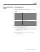
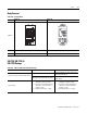
Terminal Arrangements
Table P.C — Terminal Arrangements
Series A Series B
900-TC8
Terminals 16...20 were changed and 1...15 were not.
900-TC16 --- No change for terminal layout
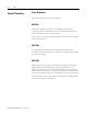
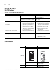
900-TC32
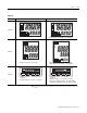
Number of terminals: 9 (1 to 9)
Input terminals: 7 to 9
RS-485 communication terminals: 5 & 6
• 100 to 240 VAC
• 24 VAC/DC (no polarity)
Number of terminals: 14 (1 to 14)
Input terminals: 10 to 12
RS-485 communication terminals: 7 & 8
CT2
One CT
Two CTs
Voltage output
Long-life relay
output
−
+
CT1
12 VDC, 21mA
+
−
A
B
B
+
V
mA
−
250 VAC, 3 A
Analog input
TC/Pt universal input
Control Output 2
Control Output 2
(Resistive load)
+
−
14
15
14
15
14
15
16
17
18
19
19
++
−
B
+
V
mA
−
−
CT1
CT2
+
−
DO NOT
USE
DO NOT
USE
B
A
DO NOT
USE
DO NOT
USE
DO NOT
USE
One CT
Two CTs
Analo
g
in
p
utTC/Pt universal in
p
ut
Control Output 2
Control Output 2
14
15
16
17
18
19
20
1
7
1212
1111
1010
9
8
2
4
3 5
6
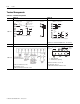
InputInput
Power Power
SupplySupply
ControlControl
Output 1Output 1
AuxillaryAuxillary
Output 1Output 1
DO NOTDO NOT
USEUSE
A
B
B
Universal
TC/Pt Input
DO NOTDO NOT
USEUSE
B(+)
A(-)
RS-495
Communications
+
-