
User guide

Publication 900-UM007D-EN-E - January 2011
3-62 Configuration & Basic Operation
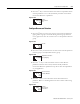
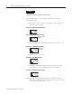
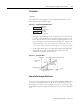
5. For this example, set 20.0. To return to the Operation function group,
press the O Key for less than one second.
Figure 3.133
Set-up of the No. 3 Display
This section describes how to configure the No. 3 Display (900-TC8). The
Multi-SP, MV or Soak Time Remain parameters can be displayed on the No. 3
display.
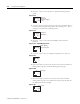
PV/SP Display Selection
The following table shows the set values and display contents for the PV/SP
Display selection.
Note: For details on configuring the MV for heating and cooling control, refer
to MV Display for Heating and Cooling Control below.
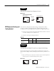
When 1, 2, 5, or 6 is selected, press the M Key to display the next value
set for the PV/SP display (display 2).
oc1
20.0
Table 3.Q — PV & SP Display Selection
Set Value Display Contents
0 Only PV/SP is displayed (with no No. 3 display.)
1 PV/SP/Multi-SP and PV/SP/MV are displayed in order.
2 PV/SP/MV and PV/SP/Multi-SP are displayed in order. )
3 Only PV/SP/Multi-SP is displayed.
4 Only PV/SP/MV is displayed.
5 PV/SP/Multi-SP and PV/SP/Soak time remain are displayed in order.
6
PV/SP/MV and PV/SP/Soak time remain are displayed in order.
7
Only PV/SP/Soak time remain is displayed.
A 2-level display is configured when shipped from the factory. (set value: 0). A
3-level display is activated if parameters are initialized. (set value: 4)