
User guide

Publication 900-UM007D-EN-E - January 2011
3-54 Configuration & Basic Operation
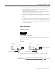
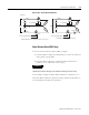
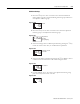
Figure 3.104 — Heater Burnout Detection
EXAMPLE
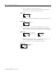
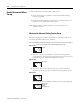
Using Two 200V AC, 2 kW Heaters, V Connecting Lines
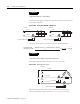
Figure 3.105 — V Connecting Lines
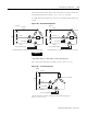
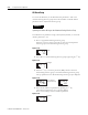
The heater burnout current when there is a burnout at the common is as
follows:
Heater burnout detection current = (10 + 5) / 2 ≈ 7.5 [A]
The heater burnout current when there is a burnout at the load is as follows:
Heater burnout detection current = (10 + 0) / 2 ≈ 5 [A]
To enable detection in either case, use 7.5 A as the heater burnout detection
current.
CT
CT
200 V
200 V
5 A→
5 A→
200 V
Load
Load
CT
CT
200 V
200 V
5 A→
5 A→
200 V
Load
Load
Burnout
Burnout
Load (such as a heater) Load (such as a heater)
Load
Load
To CT input
To CT input
Burnout
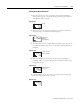
Current when there is a burnout = 10 A × (1/√3) × (√3/2) = 5 A
Current when there is a burnout = 10 A × (1/√3) × (√3/2) = 5 A
To CT Controller input To CT Controller input
CT
CT
Load
200 V
10 A
10 A→
17.3 A→
200 V
200 V
Load
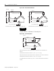
Normal
To CT input
To CT Controller input