
User guide

Publication 900-UM007D-EN-E - January 2011
3-52 Configuration & Basic Operation
EXAMPLE
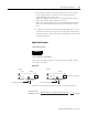
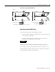
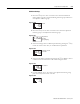
Using Three 200V AC, 1 kW Heaters
The heater power supply provides 15 A when the current is normal, and 10 A
when there is a burnout.
Figure 3.100 — Using Three 200V AZ, 1 kW Heaters
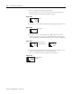
Therefore, the heater burnout detection current is calculated as follows:
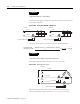
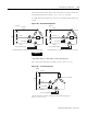
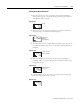
EXAMPLE
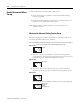
Using Three-Phase Heaters, Delta Connecting Lines
The current when each phase is normal is 17.3 A (≈ √3 × 10 A).
Figure 3.101 — Delta Connecting Lines
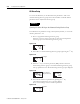
The heater burnout current when there is a burnout at the load line is as
follows: (heater burnout detection current) = (17.3 + 15) / 2 ≈ 16.1 [A]
10 A
10 A
CT
15 A→
←15 A
200 V
CT
200 V
Normal
To CT Controller input
To CT Controller input
Burnout
Load LoadLoad
Load LoadLoad
Burn-
out
Heater burnout
detection current =
(Normal current) + (Heater burnout current)
2
=
15 + 10
2
= 12.5 [A]
CT
Load
Load
200 V
200 V
17.3 A→
17.3 A→
17.3 A→
200 V
Normal
To CT input
Load
To CT Controller input