
Owner manual

Publication 8720SM-IN001A-EN-P — February 2003
18 8720SM High Performance AC Induction Motors
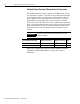
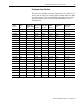
Mounting Bolt Specifications
Refer to the 8720MC High Performance Drive Integration Manual
(publication 8720MC-IN002x-EN-P) for additional motor performance
specifications.
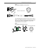
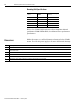
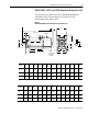
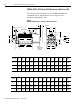
Dimensions
Within this section you will find dimension drawings for the 8720SM
motors. The following notes apply to all motor dimensional drawings:
Hole Diameter
mm (in.)
Bolt Size and
Thread
Recommended Torque
Nm (lb-ft)
12 (0.47) M10-1.5 52.9 (39)
14 (0.55) M12-1.75 90.8 (67)
15 (0.59) M12-1.75 90.8 (67)
18 (0.70) M16-2.00 226.4 (167)
19 (0.74) M16-2.00 226.4 (167)
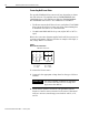
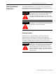
Note Description:
1 "H" Dimension will not be exceeded. Shims up to 0.5 mm (0.019 in.) thickness are usually required for coupled or geared machines .
2
Shaft extensions are according to Din 748. Tolerances are based on the ISO fitting system using K6 for diameters up to 50 mm (1.96 in.) and m6
for diameters above.
3 "GA" varies +.018/-.290 mm.
4 Walls or obstructions must not encroach on air inlet space "XI" for blower or fan cooling.
5 Tolerances for flange according to DIN42948.
6 Terminal box can be rotated in 90 degree increments and mounted on top as standard.