
Owner manual

Publication 8720SM-IN001A-EN-P — February 2003
10 8720SM High Performance AC Induction Motors
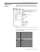
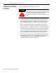
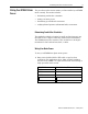
Figure 1
8720SM-005S1BASx Thru -093S6TASx Motors
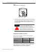
2. Connect the shield to both the motor ground and the PE ground
on the drive with an 6 mm
2
(AWG 10) or larger conductor. Refer to
the 8720MC High Performance Drive Installation Manual
(publication 8720MC-IN001x-EN-P) for the PE ground terminal on
the 8720MC drive.
Determining Your Feedback Connections
Refer to the following table to determine the motor/integrated
feedback device combination.
These feedback devices provide precision servo performance for both
spindle and power servo applications. The motor feedback cable
(2090-CDNFDMP-Sxx) shown in Figure 2 applies to the
8720SM-xxxxxxxS1, S2, and S4 motor configurations.
U/T1
V/T2
W/T3
Ground Bolt
Rotatable Conduit Box
ATTENTION
!
Connect an appropriate equipment grounding
conductor to the 8720MC drive ground
terminal, the motor frame, the transformer
enclosure if used, the drive electrical enclosure,
and an appropriate grounding electrode.
Failure to observe these precautions could
result in severe bodily injury or loss of life.
Motor Encoder Type Control Type
8720SM-xxxxxxxS3 and -xxxxxxxS4 Incremental sine/cosine Analog
8720SM-xxxxxxxS1 Single-turn absolute feedback
SERCOS
8720SM-xxxxxxxS2 Multi-turn absolute feedback