Installation Instructions 8720SM High Performance AC Induction Motors (Catalog Number 8720SM-xxxxxxxSx) Introduction This publication provides installation instructions for the 8720SM motors. Use this document if you are responsible for the design and installation of 8720SM motors. Refer to the 8720MC High Performance Drive Integration Manual (publication 8720MC-IN002x-EN-P) for performance information.
8720SM High Performance AC Induction Motors Complying with European Union Directives If this product is installed within the European Union or EEC regions and has the CE mark, the following regulations apply.
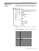
8720SM High Performance AC Induction Motors 8720SM AC Motor Overview 3 The 8720SM motors are high performance AC induction motors specifically designed for use with the Allen-Bradley 8720MC Drives. Refer to the configurator below to help identify your 8720SM motor.
8720SM High Performance AC Induction Motors 8720SM Receiving and Storage Information The customer is responsible for inspecting the equipment before accepting the shipment from the freight company. Check the items against your purchase order. Handling The 8720SM motors are equipped with lifting eye bolts. These eye bolts are provided to assist in handling and mounting the motors. The motors can accommodate either flange or foot mount. ATTENTION ! Eyebolts may unscrew during lifting.
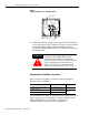
8720SM High Performance AC Induction Motors Before Mounting Your Motor 5 Before mounting your 8720SM motor, consider the following: • You can mount the motor horizontally or vertically with the shaft down or up. • The 8720SM motors are blower cooled with air flow from the blower end to the drive end. The air flow must be flowing in the direction of the arrow on the motor to provide adequate cooling. Both air inlets and outlets must be free of obstructions.
8720SM High Performance AC Induction Motors Using Belted Drives and Coupled Drives Proper alignment is key for long life of bearings, shafts and belts, and minimum downtime. Belted Drives If you use motor slide bases or rails, you must securely anchor them to the foundation with the proper bolts. Make sure the motor shaft and load shaft are parallel, and that the sheaves are aligned. When a motor is belt coupled, the belt tension must not exceed the radial load capabilities of the motor bearings.
8720SM High Performance AC Induction Motors 7 with the motor. Sheave or coupling should be balanced with a 1/2 height shaft key. Preventing Electrical Noise Use Electromagnetic Compatibility (EMC) techniques to reduce Electromagnetic Interference (EMI), commonly called noise. Noise adversely impacts motor performance by inducing stray signals. Effective techniques to counter EMI include filtering the AC power, shielding and separating signal carrying lines, and practicing good grounding techniques.
8720SM High Performance AC Induction Motors Guidelines for Installing Your Motor Observe the following for installing your motor: ATTENTION ! Publication 8720SM-IN001A-EN-P — February 2003 Only qualified electrical personnel familiar with the construction and operation of this equipment and the hazards involved should install, adjust, operate, and/ or service this equipment. Failure to observe precaution could result in severe bodily injury or loss of life.
8720SM High Performance AC Induction Motors Wiring Your 8720SM Motor Power 9 The procedures in this section assume you have installed your 8720SM motor correctly.
8720SM High Performance AC Induction Motors Figure 1 8720SM-005S1BASx Thru -093S6TASx Motors Ground Bolt V/T2 U/T1 W/T3 Rotatable Conduit Box 2. Connect the shield to both the motor ground and the PE ground on the drive with an 6 mm2 (AWG 10) or larger conductor. Refer to the 8720MC High Performance Drive Installation Manual (publication 8720MC-IN001x-EN-P) for the PE ground terminal on the 8720MC drive.
8720SM High Performance AC Induction Motors 11 Figure 2 Motor Feedback Cable (8720SM-xxxxxxxS1, S2, and S4) 83.8 (3.3) A B C P D 64 (2.5) 29.5 (1.16) L V R S E F Dimensions are in millimeters (inches) 96.52 (3.8) M N U K T J H G Viewed from Connector Face 9.65 (0.38) 2090-CDNFDMP-Sxx The mating right-angle P-Lok feedback connector shown in Figure 3 applies to the 8720SM-xxxxxxxS3 motor (and ships with each motor). This connector is designed for solder joints at each termination.
8720SM High Performance AC Induction Motors Verifying Thermal Protector (Thermostat Leads) Connections The 8720SM motors have three normally closed thermostats. There is one thermostat per phase, connected in series, with leads terminated to the feedback connector on the motor via the feedback cable. To protect against motor overheating, make sure that you connect the thermostats to the appropriate drive connector. Refer to the table below for the motor and drive pins.
8720SM High Performance AC Induction Motors Blower Motor 13 8720SM motors are blower cooled; incorporating an independently powered three-phase AC blower motor that ensures continuous air flow, regardless of the AC motor speed. ATTENTION ! The blower motor is typically wired to the AC input of the 8720MC drive and is energized even when the drive is not running. Before touching blower motor components, make sure to turn off and lock out or tag the main power supply.
8720SM High Performance AC Induction Motors Connecting the Blower Motor The specific 8720SM AC blower motor will vary depending on frame size and enclosure. The smallest motors, 8720SM-005S1BASx thru -022S2GASx, have a 547 CFM blower while the 8720SM-030S4JASx thru -093S6TASx motors have a 1117 CFM blower. In addition: • The blower motors should have a fuse in each phase. The 8720SM blower motor should use a 1 amp, time delay current limiting fuse. A Bussmann® fuse (LP-CC-1) is recommended.
8720SM High Performance AC Induction Motors Motor Operation and Maintenance 15 The standard 8720SM motors are equipped with sealed deep grove ball bearings. The motors are packed with the appropriate lubricant at the factory and do not require maintenance. ATTENTION ! ATTENTION ! Internal parts of the motor may be at line potential even when the motor is not rotating. Make sure to disconnect all power from the motor before contacting an internal part.
8720SM High Performance AC Induction Motors Specifications Environmental and Weight Specifications Specification Description Rated ambient temperature 0° to 40° C (32° to 104° F) Storage temperature -20° to 80° C (-4° to 176° F) Environmental protection IP 55 Agency certification UL/CSA/CE Available mounting methods flange/foot Weight 8720SM-005S1BxSx 75 kg (165 lb) 8720SM-007S1CxSx 91 kg (201 lb) 8720SM-011S1DxSx 102 kg (225 lb) 8720SM-015S2ExSx 131 kg (289 lb) 8720SM-018S2FASx 1
8720SM High Performance AC Induction Motors 17 Performance Specifications The motors are available with power ratings from 5.5 to 93 kW (7.5 to 125 hp) and are designed to operate with the 8720MC 380V ac to 480V ac input inverters, as well as the 8720MC regenerative power supply. The following table provides general rating information for the 8720SM motors.
8720SM High Performance AC Induction Motors Mounting Bolt Specifications Hole Diameter mm (in.) Bolt Size and Thread Recommended Torque Nm (lb-ft) 12 (0.47) M10-1.5 52.9 (39) 14 (0.55) M12-1.75 90.8 (67) 15 (0.59) M12-1.75 90.8 (67) 18 (0.70) M16-2.00 226.4 (167) 19 (0.74) M16-2.00 226.4 (167) Refer to the 8720MC High Performance Drive Integration Manual (publication 8720MC-IN002x-EN-P) for additional motor performance specifications.
8720SM High Performance AC Induction Motors 19 8720SM-005S1, -007S1, and -011S1 Dimensions (Before March 01) The following motor dimensions are for 8720SM-005S1BASx thru -011S1DCSx motors, 180 mm flange and 215 mm bolt circle manufactured before March, 2001. Figure 5 8720SM-005S1BASx thru -011S1DCSx Motor Dimensions g1 XI L T LA MS Connector Terminal Box AC I2 S P F E x1 N HD D GA HA H M AA A AB a e Blower Terminal Box 3-3/16" Dia 1-5/8" Dp C K Motor 8720SM- AB mm (in.) H1 mm (in.
8720SM High Performance AC Induction Motors 8720SM-005S1, -007S1, and -011S1 Dimensions (After March 01) The following motor dimensions are for 8720SM-005S1BASx thru -011S1DCSx motors, 180 mm flange and 215 mm bolt circle manufactured after March, 2001. Figure 6 8720SM-005S1BASx thru -011S1DCSx Motor Dimensions XI Air Space L T LA AC Terminal Box Y MS Connector X I2 S P F E N HD x1 D GA HA H M a e A AB Blower Terminal Box 3-3/16" Dia 1-5/8" Dp C K Motor 8720SM- AB mm (in.
8720SM High Performance AC Induction Motors 21 8720SM-015S2, -018S2, and -022S2 Dimensions (250 mm Flange) The following motor dimensions are for the 8720SM-015S2EASx thru -022S2GASx motors, the standard “132” with 250 mm flange and 300 mm bolt circle. Figure 7 8720SM-015S2EASx thru -022S2GASx Motor Dimensions, 250 mm Flange, L AC Y Y Encoder connector T LA XI P HD x1 N GA M H S Terminal box blower cooled only e a2 A AB m2 a a1 K E BA Motor 8720SM- AB mm (in.) H1 mm (in.) A mm (in.
8720SM High Performance AC Induction Motors 8720SM-030S4 and -037S4 Dimensions The following motor dimensions are for the 8720SM-030S4JASx thru -037S4KASx motors, 300 mm flange and 350 mm bolt circle. Figure 8 8720SM-030S4JASx thru -037S4KASx Motor Dimensions AC L Y Y Encoder connector T LA XI P HD x1 N GA M H S Terminal box blower cooled only e A AB a a1 K E BA m2 Motor 8720SM- AB mm (in.) H1 mm (in.) A mm (in.) K mm (in.) AC mm (in.) BA mm (in.) m2 mm (in.) P mm (in.
8720SM High Performance AC Induction Motors 23 8720SM-045S5, -055S5, and -063S5 Dimensions The following motor dimensions are for the 8720SM-045S5NASx thru -063S5QASx motors, 300 mm flange and 350 mm bolt circle. Figure 9 8720SM-045S5NASx thru -063S5QASx Motor Dimensions MS Connector L AC T XI g1 LA E N S P F HD M D GA x1 H I2 Blower Terminal Box (4) m2 BA a C HA AA K A e AB Motor 8720SM- AB mm (in.) H mm (in.) A mm (in.) HA mm (in.) K mm (in.) AA mm (in.) AC mm (in.
8720SM High Performance AC Induction Motors 8720SM-075S6 and -093S6 Dimensions The following motor dimensions are for the 8720SM-075S6SASx thru -093S6TASx motors. Figure 10 8720SM-075S6SASx thru -093S6TASx Motor Dimensions MS Connector L T AC g1 XI LA E S 8-Holes P N F HD D GA x1 H l2 Blower Terminal Box (4) m2 BA a C AA HA K A e AB Motor 8720SM- AB mm (in.) H mm (in.) A mm (in.) HA mm (in.) K mm (in.) AA mm (in.) AC mm (in.) C mm (in.) BA mm (in.) m2 mm (in.) P mm (in.
8720SM High Performance AC Induction Motors Motor Load Force Ratings 25 Motors are capable of operating with a sustained shaft load. The radial and axial load force locations are shown in Figure 11, and the maximum figures are in the tables. Figure 11 Load Forces on Motor Shaft Radial load force applied at center of shaft extension Axial load force The tables represent 10,000 hour L10 bearing fatigue life at various loads and speeds.
8720SM High Performance AC Induction Motors Axial Load Force Ratings (Zero Radial Load) Motor Series 8720SM- 500 RPM kg (lb) 1000 RPM kg (lb) 1500 RPM kg (lb) 2000 RPM kg (lb) 3000 RPM kg (lb) 005 307 (675) 228 (500) 187 (410) 161 (355) 100 (220) 007 307 (675) 228 (500) 187 (410) 161 (355) 100 (220) 011 307 (675) 228 (500) 187 (410) 161 (355) 100 (220) 015 284 (625) 200 (440) 160 (350) 135 (295) 75 (165) 018 284 (625) 200 (440) 160 (350) 135 (295) 75 (165) 022 284 (
8720SM High Performance AC Induction Motors 27 Publication 8720SM-IN001A-EN-P — February 2003
For more information refer to our web site: www.ab.com/motion For Allen-Bradley Technical Support information refer to: www.ab.com/support or Tel: (1) 440.646.5800 Allen-Bradley and A-B are registered trademarks of Rockwell Automation. Bussmann is a registered trademark of Cooper Industries, Inc. Publication 8720SM-IN001A-EN-P — February 2003 Copyright © 2003 Rockwell Automation. All rights reserved. Printed in USA.