
User guide


Publication 8720MC-IN002A-EN-P — December 2002
1-6 Commissioning Your 8720MC SERCOS Interface Drive
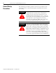
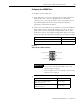
Figure 1.5
Fiber-Optic Ring Connection Example
Note: You can mount two 1756-MxxSE SERCOS interface modules
in two separate ControlLogix chassis or you can mount them
in the same chassis (as shown above).
Utilizing two 1756-MxxSE SERCOS interface modules allows
you to reduce the SERCOS ring cycle times.
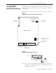
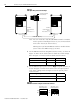
4. Set the SERCOS baud rate using DIP switches 2 and 3, as shown in
Figure 1.6. Refer to the table below for baud rate switch settings.
Refer to Figure 1.1 for the baud rate (DIP) switch location.
5. Set the SERCOS optical power level to High using DIP switch 1, as
shown in Figure 1.6. Refer to the table below for optical power
level switch settings. Refer to Figure 1.1 for the optical power
switch location.
Figure 1.6
SERCOS Baud Rate and Optical Power DIP Switches
1756
-
M
xx
SE
SERCOS
Interface Module
ControlLogix Chassis
SERCOS Fiber-Optic Ring
8720MC
High Performance
Drive
Node Address = 01
8720MC
High Performance
Drive
Node Address = 02
Receive
Tra nsm it
Receive
Transmit
Receive
Transmit
For this baud rate: Set switch 2: Set switch 3:
4M baud OFF ON
8M baud ON OFF
For this optical power level: Set switch 1:
Low OFF
High ON
1 2 3
1 2 3
DIP switches set for
4M baud applications
DIP switches set for
8M baud applications
ON
OFF
ON
OFF