8720MC High Performance Drives (Catalog Numbers 8720MC-B014, -B021, -B027, -B034, -B042, and -B048 8720MC-D065, -D078, -D097, -D120, -D149, and -D180 8720MC-RPS027, -RPS065, and -RPS190 8720MC-LR03, -LR05, -LR10, and -LR14) Integration Manual
Important User Information Because of the variety of uses for the products described in this publication, those responsible for the application and use of this control equipment must satisfy themselves that all necessary steps have been taken to assure that each application and use meets all performance and safety requirements, including any applicable laws, regulations, codes and standards.
Table of Contents Preface Introduction . . . . . . . . . . . . . . . . . . . . . . . . . Who Should Use this Manual . . . . . . . . . . . . . Purpose of this Manual . . . . . . . . . . . . . . . . . Contents of this Manual . . . . . . . . . . . . . . . . . Related Documentation . . . . . . . . . . . . . . . . . Conventions Used in this Manual . . . . . . . . . . Product Receiving and Storage Responsibility . Allen-Bradley Support . . . . . . . . . . . . . . . . . . Local Product Support . . . . . . . . . .
ii Table of Contents Optimizing the Motor Orient Procedure . . . . . . . . . . . . 2-22 Chapter 3 Troubleshooting Your 8720MC Servo Drive Chapter Objectives . . . . . . . . . . . . . . . . . . . . . . . . . . . . . Required Equipment . . . . . . . . . . . . . . . . . . . . . . . . . . . Start-up Troubleshooting Procedures. . . . . . . . . . . . . . . . Viewing the Fault Queue . . . . . . . . . . . . . . . . . . . . . . . . Fault Descriptions . . . . . . . . . . . . . . . . . . . . . . . . . . . . .
Table of Contents iii Appendix B Using the Human Interface Module (HIM) Chapter Objectives. . . . . . . . . . . . . . . . . . . . . . . HIM Display Panel and Control Panel . . . . . . HIM Display Panel Keys . . . . . . . . . . . . . HIM Control Panel Keys . . . . . . . . . . . . . HIM Control Panel Indicators . . . . . . . . . . HIM Operation . . . . . . . . . . . . . . . . . . . . . . . . . Initial Status Display . . . . . . . . . . . . . . . . . . . Choosing a HIM Mode . . . . . . . . . . . . . . . . .
iv Table of Contents Appendix D 8720SM Motor Specifications and Chapter Objectives . . . . . . . . . . . . . . . . . . . . . . . . . . . . . . D-1 Common Specifications . . . . . . . . . . . . . . . . . . . . . . . . . . D-2 Performance Curves 8720MC 750V dc Input Drive Amplifier Specifications. . D-2 8720MC I/O Specifications . . . . . . . . . . . . . . . . . . . . . D-3 Feedback Specifications . . . . . . . . . . . . . . . . . . . . . . . D-3 8720SM Motor Specifications . . . . . . . . . . . . . . . . .
Preface Introduction Who Should Use this Manual Read this preface to familiarize yourself with the rest of the manual.
P-2 Preface Contents of this Manual Refer to the following listing for the descriptive contents of this installation manual. Chapter Publication 8720MC-IN002A-EN-P — December 2002 Title Contents Preface Describes the purpose, background, and scope of this manual. Also specifies the audience for whom this manual is intended.
Preface Related Documentation P-3 The following documents contain additional information concerning related Allen-Bradley products. To obtain a copy, contact your local Allen-Bradley office, distributor, or download them from TheAutomationBookstore.com.
P-4 Preface Product Receiving and Storage Responsibility You, the customer, are responsible for thoroughly inspecting the equipment before accepting the shipment from the freight company. Check the item(s) you receive against your purchase order. If any items are obviously damaged, it is your responsibility to refuse delivery until the freight agent has noted the damage on the freight bill. Should you discover any concealed damage during unpacking, you are responsible for notifying the freight agent.
Preface Allen-Bradley Support P-5 Allen-Bradley offers support services worldwide, with over 75 Sales/ Support Offices, 512 authorized Distributors and 260 authorized Systems Integrators located throughout the United States alone, plus Allen-Bradley representatives in every major country in the world.
P-6 Preface Publication 8720MC-IN002A-EN-P — December 2002
Chapter 1 Commissioning Your 8720MC SERCOS Interface Drive Chapter Objectives This chapter provides you with information to configure and apply power to your 8720MC SERCOS interface drive.
1-2 Commissioning Your 8720MC SERCOS Interface Drive General Startup Precautions The following precautions pertain to all of the procedures in this chapter. Be sure to read and thoroughly understand them before proceeding. ATTENTION ! ATTENTION ! Publication 8720MC-IN002A-EN-P — December 2002 This product contains stored energy devices. To avoid hazard of electrical shock, verify that all voltages on the system bus network have been discharged before attempting to service, repair or remove this unit.
Commissioning Your 8720MC SERCOS Interface Drive Locating 8720MC Connectors and Indicators 1-3 8720MC connectors and indicators are located as shown in figures 1.1 and 1.2 below. You must remove the front cover to gain access to the control board. Note: Only drives with the enclosure option (-AA) have a front cover. Figure 1.
1-4 Commissioning Your 8720MC SERCOS Interface Drive Locating SERCOS Interface Module Connectors Use the figure below to locate the 1756-MxxSE SERCOS fiber-optic connectors. The fiber-optic ring is connected using the SERCOS Receive and Transmit connectors. Figure 1.
Commissioning Your 8720MC SERCOS Interface Drive 1-5 Configuring Your 8720MC Drive To configure your 8720MC drive: 1. Verify that there is no power applied to the 8720MC and that the SERCOS fiber-optic cables are plugged into the Tx and Rx connectors. To verify your fiber-optic cable connections, refer to the 8720MC High Performance Drive Installation Manual (publication 8720MC-IN001x-EN-P). 2. Set the base node address for the 8720MC by setting the SERCOS Node Address switch.
1-6 Commissioning Your 8720MC SERCOS Interface Drive Figure 1.5 Fiber-Optic Ring Connection Example 1756-MxxSE SERCOS Interface Module ControlLogix Chassis Transmit Receive 8720MC High Performance Drive Node Address = 01 Transmit 8720MC High Performance Drive Node Address = 02 Receive Transmit Receive SERCOS Fiber-Optic Ring Note: You can mount two 1756-MxxSE SERCOS interface modules in two separate ControlLogix chassis or you can mount them in the same chassis (as shown above).
Commissioning Your 8720MC SERCOS Interface Drive Configuring Your 1756-MxxSE SERCOS Interface Module 1-7 This procedure assumes that you have wired your 8720MC system and have configured the 8720MC baud rate and optical power switches. Note: For detailed configuration information, refer to the ControlLogix Motion Module Setup and Configuration Manual (publication 1756-UM006x-EN-P).
1-8 Commissioning Your 8720MC SERCOS Interface Drive 6. Select Controller Properties in the edit menu. The Controller Properties window opens. 7. Select the Date and Time tab. 8. Check the box Make this controller the Coordinated System Time master. IMPORTANT Only one ControlLogix processor can be assigned as the Coordinated System Time master. 9. Select OK. 10. Right-click on I/O Configuration in the explorer window and select New Module. The Select Module Type window opens. 11.
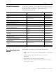
Commissioning Your 8720MC SERCOS Interface Drive 1-9 13. Select Next until the following screen opens. 14. Select Data Rate, Cycle Time, and optical power Power settings. • Ensure the Data Rate setting matches DIP switches 2 and 3 (baud rate) as set on the 8720MC control board, or use the Auto Detect setting. • Set the Cycle Time according to the table below. ControlLogix Data SERCOS Module Rate Mbit/s 4 1756-M08SE 8 SERCOS Ring Cycle Time ms Number of Axes 0.5 2 1.0 4 2.0 8 0.5 4 1.0 2.
1-10 Commissioning Your 8720MC SERCOS Interface Drive 17. Select your 8720MC-xxxx drive. 18. Select OK. The Module Properties window opens. 19. Provide/select the following Module Properties attributes: • Module name • Base Node address • Electronic Keying option 20. Select Next until the following window opens. 21. Select the New Axis button. The New Tag window opens. 22. Provide/select the following New Tag attributes: • Axis name • AXIS_SERVO_DRIVE as the Data Type 23.
Commissioning Your 8720MC SERCOS Interface Drive 1-11 25. Select None as the Bus Regulator Catalog Number (shunt option). 26. Select Finish. 27. Repeat steps 16-26 for each 8720MC-xxxx drive. The axes appear under the Ungrouped Axes folder in the explorer window. 28. Right-click Motion Groups in the explorer window and select New Motion Group. The New Tag window opens. 29. Name the new motion group. 30. Select OK. New group appears under the Motion Groups folder. 31.
1-12 Commissioning Your 8720MC SERCOS Interface Drive Applying Power to Your 8720MC This procedure assumes you have finished configuring your 8720MC drive and 1756-MxxSE SERCOS interface module. ATTENTION ! To avoid damage to your 8720SM motor, apply power to the 8720SM blower motor and verify the direction of air flow before applying power to your 8720MC drive.
Commissioning Your 8720MC SERCOS Interface Drive 1-13 3. Apply three-phase input power to the 8720MC-RPS. Refer to the 8720MC Regenerative Power Supply User Manual (publication 8720MC-RM001x-US-P) for power up procedure and troubleshooting. 4. Wait for 8720MC-RPS to finish initialization and close the (MC) contactor. Bus voltage is now supplied to 8720MC drive. 5. Observe the Drive Status LED. If the Drive Status LED is: Status: Do This: Flashing green Normal condition Go to step 6.
1-14 Commissioning Your 8720MC SERCOS Interface Drive Applying Power to Your 8720MC (without 8720MC-RPS) This procedure assumes that you have finished configuring your 8720MC drive and 1756-MxxSE SERCOS interface module. IMPORTANT Follow this procedure if your 8720MC system does not include a Regenerative Power Supply (8720MC-RPS). To apply power to your 8720MC system: 1. Ensure cabinet disconnect switch is in the OFF position. 2. Disconnect the load to the motor(s).
Commissioning Your 8720MC SERCOS Interface Drive 1-15 6. Observe the three SERCOS LEDs on the 1756-MxxSE module. If the three SERCOS LEDs are: Status: Do This: Flashing green and red Wait for steady green on all three Establishing communication LEDs. Steady green Communication ready Go to Testing and Tuning Your Axes. 1756-MxxSE module is faulted Go to the ControlLogix Motion Module Setup and Configuration Manual (publication 1756-UM006x-EN-P) for specific instructions and troubleshooting.
1-16 Commissioning Your 8720MC SERCOS Interface Drive 4. Select the Hookup tab. 5. Select 2.0 as the number of revolutions for the test (or another number more appropriate for your application). This Test: Performs this Test: Test Marker Verifies marker detection capability as you rotate the motor shaft. Test Feedback Verifies feedback connections are wired correctly as you rotate the motor shaft.
Commissioning Your 8720MC SERCOS Interface Drive 1-17 7. Select the Test (Marker/Feedback/Command & Feedback) button to verify connections. The Online Command window opens. Follow the on-screen test instructions. When the test completes, the Command Status changes from Executing to Command Complete. 8. Select OK. 9. The Online Command - Apply Test window opens (Feedback and Command & Feedback tests only). When the test completes, the Command Status changes from Executing to Command Complete. 10.
1-18 Commissioning Your 8720MC SERCOS Interface Drive 11. Select the Tune tab. 12. Enter values for Travel Limit and Speed. In this example, Travel Limit = 5 and Speed = 10. Note: Actual value of programmed units depend on your application. 13. Check Tune boxes as appropriate for your application. 14. Apply Drive Enable Input signal (P5-14) for the axis you are tuning.
Commissioning Your 8720MC SERCOS Interface Drive 1-19 16. Select OK. The Tune Bandwidth window opens. Note: Actual bandwidth values (Hz) depend on your application and may require adjustment once motor and load are connected. 17. Select OK. 18. The Online Command - Apply Tune window opens. When the test completes, the Command Status changes from Executing to Command Complete. 19. Select OK. If: Then: Your test completes successfully, this window appears: 1. Select OK.
1-20 Commissioning Your 8720MC SERCOS Interface Drive Publication 8720MC-IN002A-EN-P — December 2002
Chapter 2 Commissioning Your 8720MC Analog Drive Chapter Objectives This chapter provides you with the information to start up and tune your 8720MC analog system.
2-2 Commissioning Your 8720MC Analog Drive General Start-up Precautions The following precautions pertain to all of the procedures in this chapter. Be sure to read and thoroughly understand them before proceeding. ATTENTION ! This product contains stored energy devices. To avoid hazard of electrical shock, verify that all voltages on the system bus network have been discharged before attempting to service, repair or remove this unit.
Commissioning Your 8720MC Analog Drive 2-3 In most cases the default values in the startup procedure are adequate, however, you can modify the values, as needed, for your application. Before You Begin In an initial start-up it is always good practice to check the motor windings before you apply power to the drive. This is done by first disconnecting the motor leads from the drive, terminals T1, T2 and T3. Use a multi-meter to check continuity between the motor leads.
2-4 Commissioning Your 8720MC Analog Drive Applying Power This procedure assumes that you have wired your 8720MC system and verified the wiring. 1. Apply 380/460V ac input power to the 8720MC-RPS or drive. The Drive Status LED on the Control PCB flashes green. In addition, the HIM becomes active and a message similar to the following appears: System Ready When you apply power to the HIM, a series of messages appears before the final System Ready message appears. 2.
Commissioning Your 8720MC Analog Drive 2-5 When you choose “Ana Spindle” or “Ana Servo” parameter 503, “AuxFdbk Type must be set to “analog ref”. For analog input applications make sure parameter 503 is set to “Analog Ref”. For analog spindle applications make sure that “Position Scaling”, parameter 76, bit 7 is set to “modulo”. When modulo is selected the “Motor Posn Fdbk”, parameter 51 will display actual motor position to whatever resolution is selected in “Rot Posn Resolut”, parameter 79.
2-6 Commissioning Your 8720MC Analog Drive Understanding Servo Loop Parameters This section provides the information you will need to select and adjust servo loop parameters. One of the most important tasks to be performed during startup is the adjustment of the servo loop parameters. Adjustment of these parameters is essential to get the maximum performance from a drive application. The 8720MC is supplied with a set of default parameters which are intended to provide a good starting point.
Commissioning Your 8720MC Analog Drive 2-7 3. Press ENTER. Press either the up or down arrow key until the following appears: Choose File Procedure 4. Press ENTER. Press either the up or down arrow key until the following appears: Choose Group Parameter Switch 5. Press ENTER. Press either the up or down arrow key until you have located “Select Param Set”, parameter 217. 6. Press SEL and the number on the bottom line will flash. Use the up or down arrow key to change the number to 4 and press ENTER. 7.
2-8 Commissioning Your 8720MC Analog Drive Setting the Servo Loop Parameters Each group of servo loop parameters can have its own set of values for mode of operation, velocity limits and torque limits. In the analog version of the 8720MC drive, the mode of operation can be set for either velocity or torque modes. The parameter for making this selection for group 0 is parameter 32, “Primary Op Mode0”.
Commissioning Your 8720MC Analog Drive Auto Tuning Your 8720MC Drive 2-9 This section provides the information you need to auto tune your 8720MC drive. This procedure assumes that you have wired your 8720MC drive and have completed the procedures already covered in this chapter. Before You Perform an Auto Tune Observe the following guidelines before auto tuning your drive. • The Drive Status LED must be flashing green to indicate the bus voltage is up.
2-10 Commissioning Your 8720MC Analog Drive For the analog configuration, auto tuning will automatically calculate the following Group 0 Servo Loop parameters: Parameter 100, “Vel Prop Gain 0”; Parameter 101, “Vel Integ Time 0”; Parameter 523, “System Accel 0”; Parameter 562, “Torq Lowpas Frq0” and “Pos Loop Gain 0”. Before initiating the auto tune procedure, ensure that the Parameter 546, “Atune Config”, has the four lowest significant bits set to one.
Commissioning Your 8720MC Analog Drive 2-11 Analog Inputs and Outputs The 8720MC has two ±10V dc analog outputs and two ±10V dc analog inputs. The analog inputs are only available in the analog input spindle or power servo software configurations (parameter 501). In the SERCOS configuration the analog inputs are used to interface to the auxiliary, spindle, or axis mounted feedback device that is connected to the auxiliary feedback connector.
2-12 Commissioning Your 8720MC Analog Drive Figure 2.1 Analog Input and Output Connection Diagram CNC Drive Enable Regen P.S. Run 8720MC HIGH PERFORMANCE DRIVE 8720MC-Bxxx or -Dxxx Auto Enable (P514) +24V dc Drive Enable (Input 1) (P1-14) Analog Input 1 Auto Ref from Motion Controller 2.
Commissioning Your 8720MC Analog Drive 2-13 The analog input assignments are fixed. In the SERCOS configuration, the analog inputs are not available since the velocity or position command is provided by the SERCOS fiber-optic ring. In their place a second feedback channel is provided for spindle or axis mounted feedback devices.
2-14 Commissioning Your 8720MC Analog Drive Refer to the tables below for the linking relationship between the 8720MC I/O event variables and the digital output parameters.
Commissioning Your 8720MC Analog Drive 2-15 4. Press ENTER. Press either the up or down arrow key until the following appears Choose Group Analog Inputs 5. Press ENTER. Use the up and down arrow keys to find Parameter 695, “Analog Vel Scale”. 6. Press SEL to select the numerical value. 7. Use the up and down arrow keys to change the numerical value. 8. To change the motor direction for a given analog voltage input, press SEL to highlight the sign character. 9.
2-16 Commissioning Your 8720MC Analog Drive 4. Press ENTER. Press either the up or down arrow key until the following appears: Choose Group Analog Inputs 5. Press ENTER. Use the up and down arrow keys to find Parameter 696, “Manual Vel Scale”. 6. Press ENTER. The following message appears: Manual Vel Scale + 1000 RPM 7. Press SEL. The cursor moves to the bottom line. Continue pressing SEL until the cursor moves to the digits that you need to change. 8.
Commissioning Your 8720MC Analog Drive Operating in Manual Mode Using Digital I/O Interface 2-17 This section provides the information you need to operate your 8720MC drive in manual mode using a digital I/O interface. Before beginning this procedure, scale the manual velocity analog reference for the desire speed range and shaft direction. To operate the 8720MC drive in manual mode using digital I/O interface: 1.
2-18 Commissioning Your 8720MC Analog Drive Start-up of Motor Orient This section provides the information you will need to orient your motor. The motor orient procedure provides a means of positioning the motor to a precise location regardless of whether the motor is starting from standstill or rotating at high speed. The procedure that follows assumes that the motor feedback device is an SNS-60 Sincoder (8720SM-xxxxxxxS3, 8720SM-xxxxxxxS4 motors).
Commissioning Your 8720MC Analog Drive 2-19 4. Navigate to Parameter 154, “Orient Options” and select an orient direction. The application will dictate this choice. The available options are “CW”, “CCW” or “Shortest Pth”. 5. Enable the drive. 6. Toggle the orient request input, P5-32, to a true state or navigate to Parameter 152, “Spin Orient Req” and select a state of “1” and press ENTER.
2-20 Commissioning Your 8720MC Analog Drive complimentary offset value to assure there are no direction reversals during the orient. Assuming modulo scaling is selected the complimentary offset value is defined as the number of resolution units set in Parameter 79, minus the modulo position value in parameter 51, “Motor Posn Fback”. A simple rule of thumb is to use the complimentary offset value if the orient direction is CCW.
Commissioning Your 8720MC Analog Drive 2-21 • Once achieving the “At Program Speed” state, Parameter 330, the drive will find the marker. After detecting the marker it will change to positioning mode and determine the desired end point. In this case it determines it must continue rotating in CCW direction for another 7500 counts. • At this time the drive will issue the “Orient Complete” event, Parameter 583. The motor will be locked in the orient position until the orient request is removed.
2-22 Commissioning Your 8720MC Analog Drive Optimizing the Motor Orient Procedure This section provides the information you need to optimize your motor’s orientation: Usually motor orient cycle time is a critical issue. It is therefore important to adjust the parameters to get the most out of the drive and motor. The 8720MC is capable of high accelerations, speeds and torques therefore the mechanical systems usually become the limit.
Chapter 3 Troubleshooting Your 8720MC Servo Drive Chapter Objectives Required Equipment 1 This chapter provides information to help you determine the cause of a drive fault or improper 8720MC Drive operation and define possible corrective actions.
3-2 Troubleshooting Your 8720MC Servo Drive Start-up Troubleshooting Procedures Before installing fuses into the AC input lines of the drive or regenerative power supply, if supplied, first check that the incoming AC voltage falls within the range of 324 to 505 Vrms across each of the three phases. Make sure the AC or DC power inputs are properly wired per the 8720MC High Performance Drive Installation Manual (publication 8720MC-IN001x-EN-P).
Troubleshooting Your 8720MC Servo Drive Viewing the Fault Queue 3-3 Control Status mode on the HIM or Explore/Device Properties/Faults tab in DriveExplorer let you view the fault queue. To view the fault queue on the HIM: 1. Press any key from the status display. “Choose Mode” is shown. 2. Press the increment up key or the decrement down key to show “Control Status”. 3. Press enter to select Control Status 4. Press the increment up key or the decrement down key until “Fault Queue” is displayed. 5.
3-4 Troubleshooting Your 8720MC Servo Drive Fault Descriptions When a fault occurs, the fault is displayed until you initiate a Drive Error Reset from the digital I/O or depress the stop button from the HIM module or by executing MSFR from RSLogix 5000 if used with SERCOS. The following table provides a list of the faults, their probable causes and the drives response to the faults.
Troubleshooting Your 8720MC Servo Drive Fault Message RSLogix (HIM) DriveOvertempFault (A1: Overtemp) MotFeedbackFault (A1: Fdbk 1 Loss) Probable Cause/Drive Response A drive heat sink temperature has exceeded the specified limit. / Regen stop The motor encoder feedback signal has been lost. / Disable stop: the drive will disable and the motor will coast to a stop with an error message on the HIM. The control board status LED will be flashing and the drive OK output will be open.
3-6 Troubleshooting Your 8720MC Servo Drive Fault Message RSLogix (HIM) Probable Cause/Drive Response Corrective Actions Base driver board hardware Failure Fatal error - replace base driver board Control board hardware Failure Fatal error - replace control board Control board hardware Failure Fatal error - replace control board Control board hardware Failure Fatal error - replace control board Control board hardware Failure Fatal error - replace control board Control board software error Fat
Troubleshooting Your 8720MC Servo Drive Understanding the Fault Parameters 3-7 Using the HIM module or DriveExplorer is an effective way of finding the source of a drive fault. Several of the parameters are specifically designed to annunciate drive status and faults. The following is a description of the fault parameters. The 12 character fault messages are shown in italics. Parameter 11 - Shutdown Errors This parameter is a bit pattern that identifies any active major fault within the drive.
3-8 Troubleshooting Your 8720MC Servo Drive To view the fault parameters in Display mode on the HIM: 1. Press any key from the status display. “Choose Mode” is shown. 2. Press the increment up key or the decrement down key to show “Display”. Press the enter key to select it. 3. Press the increment or decrement key to find “Status/Faults”. Press the enter key to select the file 4. Press the increment up key or the decrement down key until “Errors” is displayed. 5.
Troubleshooting Your 8720MC Servo Drive 3-9 Parameter 13 - Drive Status This parameter is a bit pattern that identifies the status of the drive the drive.
3-10 Troubleshooting Your 8720MC Servo Drive spindle speed - “Spd Above Mx”, Event parameter 340, Setup parameter 221 Bit 11 = Reserved Bit 12 = Reserved Bit 13 = Reserved Bit 14 = Reserved Bit 15 = AB Specific Parameter 129 - 8720MC Drive Errors This parameter is a bit pattern that identifies drive error conditions that are in addition to the shutdown faults in parameter 11. The structure of parameter 129 is: If any bit is true an error is indicated.
Troubleshooting Your 8720MC Servo Drive 3-11 Bit 14 = Drive hardware - “Drv hardware” Bit 15 = Motor overspeed - “Overspeed” Troubleshooting the Digital I/O In troubleshooting the digital I/O interface it is often necessary to monitor the status of the digital and analog inputs and outputs to determine the source of the problem. The following parameters can be used for this purpose. Parameter 666 - Digital Output Status Bit 0 corresponds to Output 1 and bit 9 corresponds to Output 10.
3-12 Troubleshooting Your 8720MC Servo Drive Parameters 691 and 692 - Analog Input 1 Value and Analog Input 2 Value These parameters may be used to display the analog inputs as the 8720MC sees them. The scaling is.00% to 100.00% where 100% = 10 volts. The displayed values include the associated analog offsets, Parameters 693 and 694. Troubleshooting SCANport I/O Two parameters are available to monitor the SCANport command and status information exchange, parameters 717 and 718.
Troubleshooting Your 8720MC Servo Drive 3-13 Display mode on the HIM or DriveExplorer allows the user to view the command bits. Parameter 718 - SCANport Logic Status The 8720MC drive sends a status word to any SCANport connected device via a SCANport communications adapter. This may used by an A-B PLC to monitor the status of the drive. This may also be used for diagnostic purposes. The structure of parameter 718 is as follows. The 12 character status messages are shown in italics.
3-14 Troubleshooting Your 8720MC Servo Drive Parameter 716 - SCANport Logic Mask This parameter may be used to prevent any SCANport device from controlling the drive. The structure of parameter 716 is as follows: If a bit is set true (1) the device interface is enabled.
Troubleshooting Your 8720MC Servo Drive Troubleshooting the 8720MC-RPS Regenerative Power Supply 3-15 The 8720MC-RPS regenerative power supply is equipped with a 4 character display, 6 LEDs and 5 function keys. The display can be used to monitor incoming AC voltage, outgoing DC bus voltage, input current to the RPS, output power in kW and % RPS load. In addition the display can be used to view the RPS error log which can contain up to 10 error messages in the form of fault codes.
3-16 Troubleshooting Your 8720MC Servo Drive Supplemental Troubleshooting Information This section provides information for accessing and changing parameters not accessible through RSLogix 5000 software. Tools for Changing Parameters Most parameters are accessible through RSLogix 5000 software. Alternatives to RSLogix 5000 software for changing parameters include the DPI compatible Human Interface Module (HIM), the SCANport HIM, and DriveExplorer software. Refer to the table below for catalog numbers.
Troubleshooting Your 8720MC Servo Drive 3-17 Changing Parameters Using the DPI HIM When using the HIM to monitor or change parameters, use the up and down arrows (∧ and ∨) to arrive at selections. Refer to the instructions that came with your HIM for more information. To monitor or change parameters using the DPI HIM: 1. Select Parameter from main menu. Press ↵. 2. Select parameter number. Press ↵. 3. Enter new value. Press ↵.
3-18 Troubleshooting Your 8720MC Servo Drive Using Analog Test Points to Monitor System Variables There are two analog output test points accessible from the P4 connector (refer to Figure 1.1 for connector location). P4 Pin Description Signal P4-1 Analog Output 1 ANAOUT_CH1 P4-6 Analog Output Common ANA_COM P4-5 Analog Output 2 ANAOUT_CH2 P4-6 Analog Output Common ANA_COM Figure 3.
Troubleshooting Your 8720MC Servo Drive 3-19 To monitor dynamic system variables on analog outputs, use the values shown in the table below. Attribute Parameter Number Velocity Feedback1 0040 Velocity Commanded1 0036 Torque Feedback2 0084 Torque Commanded2 0080 Following Error3 0189 1 Velocity Command and Feedback scaling value is 0.25V = 1000 rpm (using default scaling). 2 Torque Command and Feedback scaling value is 0.
3-20 Troubleshooting Your 8720MC Servo Drive Publication 8720MC-IN002A-EN-P — December 2002
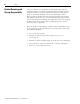
Chapter 4 SCANport Command Interface Chapter Objectives SCANport Overview 1 This chapter includes a description of the SCANport command interface. The following topics are covered: • SCANport Overview • SCANport Command Reference SCANport is a Rockwell Automation peripheral communication network which is used by the 8720MC to communicate with the integral HIM, a remote HIM, a PC running DriveExplorer in a Windows environment or an Allen-Bradley PLC.
4-2 SCANport Command Interface Figure 4.1 SCANport Peripheral Interface DeviceNet Adapter Module 1203-GK5 8720MC Drive PLC Processor Embedded HIM Option (port 6) Red = V+ White + CAN H Shield Blue = CAN L Black = Common Remote HIM 1203-SSS DPI/SCANport Connector (port 2) SCANport Expander 1203-SG2 - Two Port Expander 1203-SG4 - Four Port Expander Notebook, Desktop, or Handheld PC with DriveExporer The 8720MC external SCANport connection uses the Port 2 address.
SCANport Command Interface SCANport Command Reference 4-3 For applications where a digital communications network interface is the preferred interface, one of the Allen-Bradley 1200 series SCANport adapter modules must be used. Regardless of the control network the method of passing data to and from the drive is the same. Figure 4.2 illustrates the nature of the data exchanged. The illustration uses DeviceNet as an example of a open communication network. Figure 4.
4-4 SCANport Command Interface The communication adapter allows the exchange of ten 16 bit command input words to the drive from the PLC and ten - 16 bit status output words from the drive to the PLC. SCANp_AN1_Value is the parameter location (parameter 713) where the incoming velocity or torque command value, as received from the adapter, is stored.
SCANport Command Interface 4-5 Jog Request - If the drive is stopped (disabled via bit 00 of the command word) and the jog command bit is set true (rising edge) and there are no faults, the drive will assert the jog reference enabled state and follow SCANport jog reference command on SCANport adapter Input Word 2. The drive will continue to follow the jog reference until the jog is released. It will then regenerate to a stop.
4-6 SCANport Command Interface Parameter Set Select bit 0, 1 and 2 - Setting these 3 binary bits determines which parameter set is in use and /or which motor winding is selected. The choices are: 000 = low 0, 001 = low1, 010 = low 2, 011 = low 3 100 = high 0, 101 = high1, 110 = high 2. 111 = high 3 Parameter Strobe - When the parameter strobe bit is set momentarily the preselected parameter set number (bits 5, 6 and 7) will be selected and the associated parameters will be enabled.
SCANport Command Interface 4-7 Rotation Direction - The rotation direction bit is used to identify the direction of motor rotation. Manual Reference Selected - Whenever the digital or SCANport interfaces select the manual reference the drive acknowledges this state by setting the manual reference selected bit 15, SCANport Output Status Word. The table below describes the fixed assignments for the eight 16 bit input data words and the eight 16 bit output data words.
4-8 SCANport Command Interface Publication 8720MC-IN002A-EN-P — December 2002
Appendix A Interconnect Diagrams Chapter Objectives This appendix contains the 8720MC interconnect diagrams. The following diagrams are included: 8720MC Interconnect Diagrams • Power Interconnect Diagrams • External Active Shunt Module Interconnect Diagrams • Drive/Motor Interconnect Diagrams • 8720MC Drive and 1756-M02AE Interconnect Diagram This section provides interconnect diagrams to assist you in wiring the 8720MC system.
A-2 Interconnect Diagrams Power Interconnect Diagrams The interconnect power wiring for the 8720MC drive is shown in figures A.1, A.2, and A.3. In the configuration below, the 8720MC drive is shown with 380/460V ac (three-phase) input. This configuration applies only to the 8720MC-B021, -B027, -B034, -B042, and -B048 drives. Figure A.
Three-Phase AC Line Filter Note 3 24V AC/DC or 120V AC, 50/60 Hz CR1* Start * R S Customer supplied 120V ac M1* Note 6 CR1* MC Line Reactors Refer to Attention statement (Note 10) Stop * * INDICATES USER -SUPPLIED COMPONENT T E/N Note 11 Bonded Cabinet Ground Bus* Harmonic Filter To Motor Fan Varistor Motor Fan Fusing* Input Fusing * Three-Phase Input (+10/-15%) 380V ac RMS, 50 Hz or 460V ac RMS, 60 Hz Note 1, 2 T1 S1 R1 T S R G MC2 MC1 PR3 PR2 PR1 L3 AUX L2 AUX TB2 L1 A
A-4 Interconnect Diagrams In the configuration below, two 8720MC drives are shown with the 8720MC-RPS and 750V dc (common bus) input. This configuration applies to all 8720MC drives. Figure A.
Interconnect Diagrams A-5 8720MC HIGH PERFORMANCE DRIVE 8720MC-Bxxx and -Dxxx Drive 1 Note 15 TB4 +24V DC +24V DC_COM DC Bus Fusing* TB4-1 +24V dc Auxiliary Logic Power Connections* TB4-2 TB1 DC+ From 8720MC-RPS DC Bus Connections (TB1) Bonded Cabinet Ground Bus* DCNote 2 To Control Stop String P5 DRIVE OK+ TB1 P5-6 P5-7 DRIVE OK- L1 L2 To Motion Controller Drive Enable P5-14 DRIVE ENABLE L3 Note 13 PE R N/C S N/C T N/C 120V AC Drive Error Reset Drive Fan 120 RTN Note 9 TE P5
A-6 Interconnect Diagrams External Active Shunt Module Interconnect Diagrams In the figure below, the 8720MC is shown wired with a Bulletin 1336 external active shunt. Refer to the 8720MC High Performance Drives Installation Manual (publication 8720MC-IN001x-EN-P) for a list of external active shunt module catalog numbers available for the 8720MC. Figure A.
Interconnect Diagrams A-7 In the figure below, the 8720MC (with three-phase AC input) is shown wired with a Bulletin 1336 external active shunt (master) and two slave units. Refer to the 8720MC High Performance Drives Installation Manual (publication 8720MC-IN001x-EN-P) for a list of external active shunt module catalog numbers available for the 8720MC. Figure A.
A-8 Interconnect Diagrams Drive/Motor Interconnect Diagrams (SERCOS) This section contains the motor power, brake, and feedback signal interconnect diagrams between the 8720MC drive and the MPL-B8xxx, MPL-B9xxx, and 8720SM motors used in SERCOS interface mode. In the configuration below, the 8720MC drive is shown connected to the MPL-B8xxx or MPL-B9xxx (SERCOS mode) motors. Figure A.
Interconnect Diagrams A-9 In the configuration below, the 8720MC drive is shown connected to the 8720SM-xxxxxxxS1 or -xxxxxxxS2, (SERCOS mode) motors. Figure A.
A-10 Interconnect Diagrams Drive/Motor Interconnect Diagrams (Analog) This section contains the motor power and feedback signal interconnect diagrams between the 8720MC drive and the 8720SM motors used in analog mode. In the configuration below, the 8720MC drive is shown connected to the 8720SM-xxxxxxxS4 (analog mode) motors. Figure A.
Interconnect Diagrams A-11 In the configuration below, the 8720MC drive is shown connected to the 8720SM-xxxxxxxS3, (analog mode) motor. Figure A.
A-12 Interconnect Diagrams 8720MC Drive and 1756-M02AE Interconnect Diagram Figure A.10 provides information to assist you in wiring the 1756-M02AE servo module to your 8720MC drive. Figure A.
Appendix B Using the Human Interface Module (HIM) Chapter Objectives Refer to this chapter when using the Human Interface Module (HIM) to configure your 8720MC analog drive.
B-2 Using the Human Interface Module (HIM) HIM Display Panel and Control Panel The HIM contains a display panel and a control panel: • The display panel lets you program the drive, view the various operating parameters and monitor the drive status. • The control panel lets you perform manual control functions such as start, stop, jog and setting the manual velocity. Figure B.
Using the Human Interface Module (HIM) B-3 HIM Display Panel Keys The HIM programming panel provides the 5 keys and a 2 line by 16 character LCD display as shown in Figure B.2. Figure B.2 HIM Display/Program Keys Sys Ready +0 rpm ESC Program Panel SEL JOG Press this key: ESC SEL To: It is called: Go back one level in the menu tree that the HIM uses to organize information Escape key Alternates which display line (top or bottom) is currently active.
B-4 Using the Human Interface Module (HIM) HIM Control Panel Keys The HIM provides the eight keys for motor control in the control panel section as shown in Figure B.3. Figure B.3 HIM Control Panel Keys Sys Ready +0 rpm ESC SEL JOG Press this key: Control Panel To: It is called: If the drive is in manual mode and no other control devices are sending a Stop command, the start key will cause the motor to rotate in the HIM selected direction and velocity.
Using the Human Interface Module (HIM) B-5 HIM Control Panel Indicators The HIM control panel has the following indicators. This indicator: HIM Operation Provides information about: It is called: The direction of motor rotation Direction LED An approximate visual indication of the command manual jog speed. This indicator is only available with digital speed control. Speed Indicator Initial Status Display When you first apply power to the 8720MC Drive, the HIM cycles through a series of displays.
B-6 Using the Human Interface Module (HIM) Choosing a HIM Mode From the Initial Status Display, press any one of the five display panel keys. “Choose Mode” is displayed. Press the Increment or Decrement key to scroll through the modes. The navigation diagram for the available modes in shown Figure B.5 “HIM Menu Tree”. The HIM modes are displayed in a circular register. Depressing the increment up key selects the next mode while depressing the decrement down key selects the previous mode.
Using the Human Interface Module (HIM) B-7 Figure B.
B-8 Using the Human Interface Module (HIM) Using the Program and Display Modes The Display and Program modes let you view and modify parameters. To use these modes, follow these steps: 1. Press any key from the status display. Choose Mode is shown. 2. Press the increment up key or the decrement down key to display “Program” if you want to change the value of a parameter or “Display” if you only want to view the value of a parameter. 3. Press the enter key 4.
Using the Human Interface Module (HIM) Viewing Bit Pattern B-9 Some parameters, such as “Dig_Output_Status” (parameter 661), have a bit pattern that you can view, and in some cases, change. You can use your HIM to see what each bit means.
B-10 Using the Human Interface Module (HIM) Changing a Bit in a Bit Pattern Some of the bit pattern parameters can be changed. For example, if you wish to change the configuration selections for the auto tune procedure. First, using the increment, decrement and enter keys navigate to parameter 546 in the file “Procedure” and the group “Auto Tune”. This is a bit pattern used to select the auto tune options. Using the select key you can highlight the bit you wish to change.
Using the Human Interface Module (HIM) B-11 Restoring the Factory Default Values To reset the values of all parameters to the factory default values, first disable the drive if it is enabled, then: 1. From the EEProm mode prompt, press the increment up key or the decrement down key until “Reset Defaults” is displayed. 2. Press the enter key to restore all parameters to their original factory setting. 3. Press Escape. Reprogram Fault is displayed. 4. Press the Stop key to reset the fault.
B-12 Using the Human Interface Module (HIM) Uploading a Parameter Profile You can transfer a parameter profile from the 8720MC Drive to a remote HIM, Cat. No. 1201-HAx, as a means of transferring a parameter set from one 8720MC to another. This functionality is not available with the 8720MC built in HIM. To upload a parameter profile from the drive to the HIM: 1. From the EEProm mode prompt, press the increment up key or the decrement down key until “Drive -> HIM” is displayed. 2.
Using the Human Interface Module (HIM) B-13 Downloading a Parameter Profile To download a parameter profile from the remote HIM to a drive: The download function is only available when a valid profile is stored in the HIM. 1. From the EEProm mode prompt, press the increment up key or the decrement down key until “HIM →Drive” is displayed. 2. Press enter. A profile name (up to 14 characters) is displayed on line 2 of the HIM. 3.
B-14 Using the Human Interface Module (HIM) Using the Search Mode Search mode lets you search through the parameter list and display all parameters that are not at the factory default values. You can also search for links that are not the factory defaults. To use Search mode: 1. From the status display, press any key. “Choose Mode” is shown. 2. Press the increment up key or the decrement down key to display “Search” mode. 3. Press enter. 4.
Using the Human Interface Module (HIM) B-15 The fault queue can contain up to 32 faults. The 8720MC Drive reports the faults using the following format. Figure B.7 Fault Format Fault name A 1 F Fault queue indicator : 2 O v e 0 2 8 r T e m p T r i Fault code number T p r p 1 Position in fault queue 30386-M Using the Password Mode • The trip indicator is only present if this fault caused the drive to trip.
B-16 Using the Human Interface Module (HIM) Programming a Password When Drive Power is Applied With a Series B remote HIM, you can program Password mode to be displayed when drive power is applied. To do this, you need to press the Increment and Decrement keys simultaneously while the Password display is shown. Once you set the password, the Program/EEProm modes and the Control Logic/Clear Queue menus are password protected and are not displayed in the menu. To access these modes, you need to: 1.
Using the Human Interface Module (HIM) Creating or Changing a Link B-17 The 8720MC analog, digital and SCANport outputs can be linked to different variables within the 8720 system. The analog, digital and SCANport inputs have fixed links and cannot be modified. The outputs have default links as discussed in the 8720MC High Performance Drives Installation Manual (publication 8720MC-IN001x-EN-P). These default links were chosen to suit most spindle or power servo applications.
B-18 Using the Human Interface Module (HIM) Removing a Link You may remove an output link by setting it’s parameter address value to zero. The procedure for changing a parameter link discussed above may be used for this purpose if the parameter address value is changed to zero. Note that the displayed value will be 12 since 0 is a reserved parameter. ATTENTION ! Using DriveExplorer Be careful when removing links.
Appendix C Programming Parameters Chapter Objectives Understanding the Parameter Files, Groups and Elements This chapter provides the following information so that you can program your 8720MC drive operating in analog mode: • Understanding the Parameter Files, Groups and Elements • Parameter Files, Groups, and Elements (Group Listing) • 8720MC Parameters (Alphabetical Listing) • Parameter Descriptions (Numerical Listing) The 8720MC Parameters are divided into 7 files to help organize the parame
C-2 Programming Parameters Parameter Files, Groups, and Elements (Group Listing) Parameter Number Element Name This section provides parameters supported by the 8720MC drive listed by group, file, and element.
Programming Parameters Parameter Number Element Name Parameter Number Element Name Parameter Number Element Name Parameter Number C-3 Element Name File: Group File: Group File: Group File: Group Procedure: Auto Tune Motor/Drive/Fdbk: Motor Data Motor/Drive/Fdbk: Aux Feedback I/O Interface: Analog Inputs 541 ATune Select 777 Motor Select 115 Aux Fdbk Config 691 AnaInput 1 Value 542 ATune Torq Limit 141 Motor Data 117 Aux Fdbk Resol 692 AnaInput 2 Value 543 ATune Vel Limit
C-4 Parameter Number Programming Parameters Element Name Parameter Number Element Name Parameter Number Element Name Parameter Number Element Name File: Group File: Group File: Group File: Group Servo Loop: Group 0 Servo Loop: Group 2 Servo Loop: Group 4 Servo Loop: Group 6 505* OP Mode 0 831* OP Mode 2 871* OP Mode 4 911* OP Mode 6 38 +Vel Limit 0 832 +Vel Limit 2 872 +Vel Limit 4 912 +Vel Limit 6 39 -Vel Limit 0 833 -Vel Limit 2 873 -Vel Limit 4 913 -Vel Limit 6 1
Programming Parameters 8720MC Parameters (Alphabetical Listing) C-5 This section provides parameters supported by the 8720MC drive (in alphabetical order by parameter description). Each parameter is cross-referenced to the associated file and group.
C-6 Programming Parameters Parameter Number Description 16 Character Name File Group 106 Current Loop Proportional Gain 1 Cur Bandwidth Control Torque 380 DC Bus Voltage DC Bus Voltage Status/Faults Drive Status 95 Diagnostic Message Diagnostic Msg Status/Faults Errors 690 Digital Input Status Bytes Input Image I/O Interface Digital Inputs 662 Digital Output 1 Output 01 Source I/O Interface Digital Outputs 671 Digital Output 10 Output 10 Source I/O Interface Digital Outpu
Programming Parameters C-7 Parameter Number Description 16 Character Name File Group 109 Motor Peak Current Mtr Peak Current Motor/Drive/Fdbk Motor Data 779 Motor Pole Count/Linear Motor Pole Pitch Motor Pole Count Motor/Drive/Fdbk Motor Data 780 Motor Rated Acceleration Mtr Acceleration Motor/Drive/Fdbk Motor Data 782 Motor Rated Continuous Power Mtr Rated Power Motor/Drive/Fdbk Motor Data 785 Motor Rated Continuous Torque/Force (TC or FC) Rated Torque Motor/Drive/Fdbk Motor
C-8 Programming Parameters Parameter Number Description 16 Character Name File Group 76 Position Data Scaling Type Pos Scaling Type Control Position 277 Position Feedback 1 Type (Motor) Mtr Fdbk Config Motor/Drive/Fdbk Motor Feedback 115 Position Feedback 2 Type (Auxiliary) Aux Fdbk Config Motor/Drive/Fdbk Aux Feedback 51 Position Feedback Value 1 (Motor Feedback) Motor Posn Fback Control Position 53 Position Feedback Value 2 (Auxiliary Feedback) Aux Posn Fback Control Positio
Programming Parameters C-9 Parameter Number Description 16 Character Name File Group 38 Positive Velocity Limit Value +Vel Limit 0 Servo Loop Group 0 532 Power Supply Utilization Pwr Sup Utilized Status/Faults Drive Status 811 Primary Operating Mode 1 OP Mode 1 Servo Loop Group 1 831 Primary Operating Mode 2 OP Mode 2 Servo Loop Group 2 851 Primary Operating Mode 3 OP Mode 3 Servo Loop Group 3 871 Primary Operating Mode 4 OP Mode 4 Servo Loop Group 4 891 Primary Operati
C-10 Programming Parameters Parameter Number Description 16 Character Name File Group 842 System Acceleration 2 System Accel 2 Servo Loop Group 2 862 System Acceleration 3 System Accel 3 Servo Loop Group 3 882 System Acceleration 4 System Accel 4 Servo Loop Group 4 902 System Acceleration 5 System Accel 5 Servo Loop Group 5 922 System Acceleration 6 System Accel 6 Servo Loop Group 6 942 System Acceleration 7 System Accel 7 Servo Loop Group 7 258 Target Position Target
Programming Parameters C-11 Parameter Number Description 16 Character Name File Group 917 Velocity Loop Integral Action Time 6 Vel Integ Time 6 Servo Loop Group 6 937 Velocity Loop Integral Action Time 7 Vel Integ Time 7 Servo Loop Group 7 100 Velocity Loop Proportional Gain Vel Prop Gain 0 Servo Loop Group 0 816 Velocity Loop Proportional Gain 1 Vel Prop Gain 1 Servo Loop Group 1 836 Velocity Loop Proportional Gain 2 Vel Prop Gain 2 Servo Loop Group 2 856 Velocity Loop Prop
C-12 Programming Parameters Parameter Descriptions (Numerical Listing) This section provides detailed definition of the parameters supported by the 8720MC drive (in numerical order by parameter number). These parameters are required to provide the basic drive functionality. Some of the parameters are read only (as indicated by the letter R in the top right corner of each parameter) and are available for display only.
Programming Parameters Name: Drive_Status Parameter No. 13 File: Status/Faults Group: Drive Status Data Display: Bit Pattern C-13 R Description: Class 3 diagnostic (C3D). Drive operation status flags. When a condition changes in the drive, the corresponding bit changes in the C3D, this sets the change bit for C3D in the SERCOS drive status (bit 11) to a binary '1'. When the C3D is read via the service channel, the C3D change bit is reset to '0'.
C-14 Programming Parameters Name: Prime_OP_Mode_n Data Display: Enumerated Selection R/W Parameter No. 32 File: Servo Loop Group: Group 0 Description: Primary operation mode - There are 8 groups of servo parameters (n = 0 - 7) and “Primary Operating Mode” is one of them.
Programming Parameters Name: -Vel_Limit_0 Data Display: Signed Decimal C-15 R/W Parameter No. 39 File: Servo Loop Group: Group 0 Description: Negative velocity limit value. This parameter describes the maximum allowable velocity in the negative direction. If the velocity limit value is exceeded, the drive responds by setting the status 'ncommand > nlimit' in C3D (see parameter 13) as well as parameter 335 “Vel_Above_Limit”. This parameter appears in 8 sets of servo loop parameters.
C-16 Programming Parameters Name: Velocity_Polarity Data Display: Enumeration of Choices R/W Parameter No. 43 File: Control Group: Velocity Description: Velocity polarity parameter. This parameter is used to switch polarities of velocity data for specific applications. Polarities are not switched internally but externally (on the input and output) of a closed loop system. The motor shaft turns clockwise when there is a positive velocity command difference and no inversion is programmed.
Programming Parameters Name: Vel_Scale_Factor Data Display: Integer C-17 R/W Parameter No. 45 File: Control Group: Velocity Description: Velocity data scaling factor. This parameter defines the scaling factor for all velocity data in a SERCOS configured drive. This parameter is available with the 8720MC SERCOS interface. Default: preferred Length 2 bytes SERCOS/DPI Min/Max Min. ≥ 1 Max.
C-18 Programming Parameters Name: +Position_Limit Data Display: Signed Integer R/W Parameter No. 49 File: Linear List Group: Linear List Description: This is the maximum allowable distance in the positive direction. When the positive position limit is exceeded, the drive sets error bit 13 of the C1D (parameter 11). Default: +32767 Length 2 bytes SCANport Min/Max Min. ≥ -32768 Max. ≤ +32767 SCANport Scaling Resolution 360/parameter 79 = rotary position increment in deg.
Programming Parameters Name: Motor_Posn_Fback Data Display: Resolution Units C-19 R Parameter No. 51 File: Control Group: Position Description: Position feedback value 1 (motor feedback). In the analog spindle and power servo configurations the feedback is always scaled for rotary feedback with modulo format using parameter scaling.
C-20 Programming Parameters Name: Posn_Polarity Data Display: Bit Pattern R/W Parameter No. 55 File: Control Group: Position Description: Position polarity parameters. This parameter is used to switch polarities of reported position data for specific applications. Polarities are switched outside (i.e. on the input and output) of a closed loop system. The motor shaft turns clockwise (when viewed from the output shaft) when there is a positive position command difference and no inversion is programmed.
Programming Parameters Name: Position Scaling Parameter No. 76 File: Control Group: Position Default: x00x01010 Data Display: Bit Pattern C-21 R/W Description: Position data scaling type. A variety of scaling methods can be selected by means of the scaling type parameter. This parameter applies to the SERCOS and 32 bit SCANport (DPI) configurations. By default the analog version uses rotational and parameter scaling.
C-22 Programming Parameters Name: Posn_Scale_Expon Data Display: Signed Integer R/W Parameter No. 78 File: Control Group: Position Description: Linear position data scaling exponent. This parameter defines the scaling exponent for all linear position data in a SERCOS configured drive. Parameter 78 applies to the SERCOS and 32 bit SCANport (DPI) configurations when preferred scaling is not used. Parameter 79, not 78, is used for analog configurations.
Programming Parameters Name: Torque_Offset Data Display: Signed Decimal C-23 R/W Parameter No. 81 File: Control Group: Torque Description: This is an additional function for torque control in the drive. The additive torque command value is added to the torque command value (parameter 80) in the drive. Default: 0.0 Length 2 bytes SCANport Min/Max Min. ≥ -1000.0 Max. ≤ +1000.0 SCANport Scaling Resolution 1=.1% Units % Default: 0.0 Length 2 bytes SERCOS/DPI Min/Max Min. ≥ -215 Max.
C-24 Programming Parameters Name: Torque_Fback Data Display: Decimal R, Link Parameter No. 84 File: Control Group: Torque Description: The torque feedback value can be is transferred from the drive to the control unit via SERCOS. Default: 0.0 Length 2 bytes SCANport Minimum/ Maximum Min. ≥ -1000.0 Max. ≤ +1000.0 SCANport Scaling Resolution 1=.1% Units % Default: 0 Length 2 bytes SERCOS/DPI Min/Max Min. ≥ -215 Max.
Programming Parameters Name: Torq_Scale_Type Data Display: Bit Pattern C-25 R/W Parameter No. 86 File: Control Group: Torque Description: Torque/force data scaling type. In the SERCOS configuration a variety of scaling methods can be selected by means of this scaling type parameter. In the analog configuration percent scaling of motor torque is the only available choice.
C-26 Programming Parameters Name: ±Torque_Limit Data Display: Signed Decimal R/W Parameter No. 92 File: Control Group: Torque Description: Sets the torque limit symmetrically in both directions. When the actual torque exceeds this value, bit 4 in C3D (parameter 13) is set. Default: 0.0 Length 2 bytes SCANport Min/Max Min. 0.0 Max. ≤ +1000.0 SCANport Scaling Resolution 1=.1% Units % Default: 0 Length 2 bytes SERCOS/DPI Min/Max Min. ≥ -215 Max.
Programming Parameters Name: Diagnostic_Msg Data Display: ASCII Characters C-27 R Parameter No. 95 File: Status/Faults Group: Errors Description: Any drive-specific message concerning the operation of the drive can be stored here, and the master can read it at any time. Default: N/A Length Variable Characters Minimum/Maximum N/A Name: Drive_Err_Reset Parameter No.
C-28 Programming Parameters Name: Modulo_Value Data Display: Integer R/W Parameter No. 103 File: Control Group: Position Description: Modulo value. In the SERCOS configuration if the modulo format is selected in the position scaling parameter (parameter 76), the modulo value defines the range that the drive & control must implement. This value determines the roll over point of a modulo axis. In the analog configuration the position data scaling type is always rotary axis.
Programming Parameters Name: Cur_Bandwidth Data Display: unsigned Integer C-29 R Parameter No. 106 File: Control: Group: Torque Description: This attribute defines the tuned bandwidth setting so that the current regulator’s KP and KI can be derived. Default: 2000 Length 2 bytes Minimum/Maximum Min. > .1 Max. ≤ 6553.5 Name: Mtr_Peak_Current Scaling Resolution 1 = 1 rad/s Units rad/s Data Display: Decimal R/W Parameter No.
C-30 Programming Parameters Name: Mtr_Cont_Current Data Display: Decimal R/W Parameter No. 111 File: Motor/Drive/ Fdbk Group: Motor Data Description: The motor continuous stall current is the current at which the motor produces the continuous standstill torque according to the motor spec sheet. For all motors except for asynchronous motors, this parameter is used as a reference for all torque data and for determining motor-related current values.
Programming Parameters Name: Mtr_Torq_Overld Data Display: Signed Decimal C-31 R/W Parameter No. 114 File: Linear List Group: Linear List Description: When the load limit is exceeded for a period of time, the overload shut-down bit 0 of C1D (parameter 11) is set. Default: 100.0 Length 2 bytes SCANport Min/Max Min. > 0 Max. ≤ 1,000 SCANport Scaling Resolution 1 = 0.1% Units % Default: 100.0 Length 2 bytes SERCOS/DPI Min/Max Min. ≥ -215 Max.
C-32 Programming Parameters Name: Gear_Out_Revs_0 Parameter No. 122 File: Servo Loop Group: Group 0 Data Display: Integer R/W Description: Output revolutions of load gear set. Output revolutions must be entered as an integer value. For example: If the input makes 4 turns for each output revolution, a value of 4 is entered into parameter 121 and a value of 1 is entered into parameter 122. This parameter applies to the SERCOS interface only. Analog Default: Length 1 2 bytes Analog Minimum/Maximum Min.
Programming Parameters Name: Torque_Threshold Parameter No. 126 File: Status/Faults Group: Setup Data Display: Decimal C-33 R/W Description: Torque threshold (Tx ). If the torque feedback value exceeds the torque threshold T x, the drive sets the status 'T ≥ Tx' in C3D (parameter 333). Analog Default: Length 100.0 2 bytes SCANport Min/Max Min. ≥ 0 Max. ≤ +1000.0 SCANport Scaling Resolution 1 = .1 % Units % Rated motor torq Default: 100.0 SERCOS/DPI Min/Max Min. > 0 Max.
C-34 Programming Parameters Name: +Accel_Limit_0 Data Display: Integer R/W Parameter No. 136 File: Servo Loop Group: Group 0 Description: Acceleration Limit Parameter 136 contains the desired acceleration limit for parameter set zero in radians per sec2. This parameter applies to the command reference regardless of it’s source e. g. Analog input, SCANport or HIM. Reducing the acceleration rate will prevent shocking the mechanical system while increasing the speed.
Programming Parameters Name: Motor_Data Data Display: ASCII Representation of Enumeration C-35 R Parameter No. 141 File: Motor/Drive/ Fdbk Group: Drive Data, Motor Data Description: Motor Catalog Number Parameter 141 contains the Allen-Bradley catalog number of the motor. This is a 64 character string which contains multiple display elements.
C-36 Programming Parameters Name: Spin_Orient_Req Data Display: Bit Pattern R/W Parameter No. 152 File: Procedure Group: Orient Description: Spindle Orient Procedure Command. This procedure command automatically switches the drive to internal position loop control, below the spindle orient speed (parameter 222), and initiates an orient to the defined orient position. In a SERCOS drive when bits 0 and 1 of parameter 152 are set true an orient is requested.
Programming Parameters Name: Orient_Angle Data Display: Integer C-37 R/W Parameter No. 153 File: Procedure Group: Orient Description: Spindle angle position. This parameter is the absolute spindle position angle relative to the zero position reference point as modified by the motor marker offset (parameter 150) or the spindle mounted encoder marker offset (parameter 151, SERCOS and SCANport configurations only).
C-38 Programming Parameters Name: At_Spd_Window Data Display: Integer R/W Parameter No. 157 File: Status/Faults Group: Setup Description: The velocity window relates the current velocity to the velocity command value (parameter 36). If the current velocity feedback value falls within the calculated velocity window, the drive sets the status “n feedback = n command” (parameter 330).
Programming Parameters Name: Acc_Scale_Type Data Display: Bit Pattern C-39 R/W Parameter No. 160 File: Control Group: Acceleration Description: Acceleration data scaling type. A variety of scaling methods can be selected by means of the acceleration data scaling type parameter. This parameter is used with SERCOS interface. For the analog configuration see parameter 260.
C-40 Programming Parameters Name: Accel_Exponent Data Display: Integer R/W Parameter No. 162 File: Control Group: Acceleration Description: Acceleration data scaling exponent. This parameter defines the scaling exponent for all acceleration data in a drive. Default: preferred Length 2 bytes Minimum/Maximum Min. ≥ -215 Max.
Programming Parameters Name: Mtr_Cont_Current Parameter No. 196 File: Motor/Drive/ Fdbk Group: Motor Data Data Display: Decimal C-41 R/W Description: Motor rated current. The motor rated current is the current at which the motor produces the rated torque according to the motor spec sheet. For all asynchronous motors, this parameter is used as a reference for all torque data and for determining motor related current values. Analog Default: Length Motor encoder 2 bytes SCANport Min/Max Min. ≥ 0 Max.
C-42 Programming Parameters Name: Switch_Param_Set Data Display: Bit Pattern R/W Parameter No. 216 File: Procedure Group: Parameter Switch Description: Switch parameter set procedure command. This procedure command allows the system to switch parameter sets. The drive switches to the parameter set which is programmed in the parameter set preselection (parameter 217). This parameter is used with the SERCOS interface.
Programming Parameters Name: Min_Spindle_Spd Parameter No. 220 File: Status/Faults Group: Setup Data Display: Integer C-43 R/W Description: Minimum spindle speed. When the speed falls below minimum spindle speed, the state “Speed Below Minimum” (parameter 339) is created. This event can be linked to a digital output or SCANport status bit. It can also be assigned to a real time SERCOS status bit. Analog Default: Length 10,000 2 bytes SCANport Min/Max Min. ≥ 0 Max.
C-44 Programming Parameters Name: Actual_Param_Set Data Display: Bit Pattern R Parameter No. 254 File: Procedure Group: Parameter Switch Description: Actual parameter set. This parameter stores the current active parameter set in the drive. In the SERCOS configuration if a new parameter set is to be activated, it must first be preselected using parameter set preselection (parameter 217). Parameter set 0 must be active in every drive before and during initialization.
Programming Parameters Name: Posn_Velocity Data Display: Decimal C-45 R/W Parameter No. 259 File: LInear list Group: LInear list Description: Positioning Velocity. The “positioning velocity” is used in the “drive resident position interpolation” operation mode as the positioning velocity during a DPI or SERCOS commanded change in target position, Parameter 258 Default: 1000 Length 2 bytes SCANport Min/Max Min. ≥ 0 Max.
C-46 Programming Parameters Name: Mtr_Fdbk_Config Data Display: Bit Pattern R/W Parameter No. 277 File: Motor/Drive/ Fdbk Group: Motor Feedback Description: Position feedback 1 type. The position feedback 1 type parameter refers only to a motor feedback device. This parameter is programmed to define the corresponding conditions which apply to reading the motor feedback device.
Programming Parameters Name: Velocity_Error Data Display: Decimal C-47 R, Link Parameter No. 347 File: Control Group: Velocity Description: Velocity error. The current difference between the commanded velocity and actual velocity is placed in this parameter Default: 0 Length 2 bytes SCANport Min/Max Min. ≥ -30,000 Max.
C-48 Programming Parameters Name: Mtr_Shaft_Power Data Display: Decimal R, Link Parameter No. 386 File: Status/Faults Group: Drive Status Description: Motor shaft power. The drive places the estimated motor shaft power in this parameter. Default: Length 2 bytes Minimum/Maximum Minimum Input: ≥ 0 Maximum Input: ≤ +655.35 Name: A-B_Application Parameter No. 501 File: Motor/Drive/ Fdbk Group: Drive Data Scaling Resolution 1 = .
Programming Parameters Name: AuxFdbk_Type Data Type: ASCII Characters C-49 R/W Parameter No. 503 File: Motor/Drive/ Fdbk Group: Aux Feedback Description: The feedback type for a machine mounted feedback device is found in parameter 115. The resolution of the machine mounted feedback device is found in parameter 117 for both rotary and linear devices. Parameter 503 is used to provide additional auxiliary feedback information.
C-50 Programming Parameters Name: Vel_Integ_Err Data Display: Signed Decimal R Parameter No. 516 File: Control Group: Velocity Description: This parameter contains the velocity loop integral gain multiplied by the integrator. This is the integrator’s contribution to the acceleration command. Default: 65535 Length 2 bytes SCANport Min/Max Min. ≥ 0 Max. ≤ 65535 SCANport Scaling Resolution 1 = 1rad/sec2 Units rad/sec2 Default: 0.0 Length 4 bytes SERCOS/DPI Min/Max Min. ≥ -231 Max.
Programming Parameters Name: +Dyn_Iq_Limit Data Display: Signed Decimal C-51 R/W Parameter No. 519 File: Control Group: Torque Description: The positive dynamic Iq limit defines the maximum positive torque producing current available in the motor/inverter system. A value of +100% is defined as the motor or drive rated current, whichever is less.
C-52 Programming Parameters Name: System_Accel_0 Data Type: Integer R/W Parameter No. 523 File: Servo Loop Group: Group 0 Description: The 8720MC supports 8 sets of Servo Parameters (0-7). The SERCOS link, the I/O interface or SCANport can select which set of parameters is to be enabled. Group 0 is the default group. Parameter 523 is used to provide the drive with the required motor acceleration that will produce 100% torque for Servo group 0.
Programming Parameters Name: Enable_Brake_Sol Data Type: Bit Flag C-53 R, Link Parameter No. 528 File: I/O Interface Group: Event Links Description: The 8720MC digital I/O can be linked to events within the drive. One of the 8720MC relay contact outputs can be linked to parameter 528. Parameter 528 is true whenever the drive is enabled and the brake delay constants (parameters 206 and 207) are satisfied.
C-54 Programming Parameters Name: -Dyn_Iq_Limit Data Display: Signed Decimal R/W Parameter No. 536 File: Control Group: Torque Description: The negative dynamic Iq limit defines the maximum negative torque producing current available in the motor/inverter system. A value of -100% is defined as the motor or drive rated current, whichever is less.
Programming Parameters Name: ATune_Vel_Limit Data Type: Decimal C-55 R/W Parameter No. 543 File: Procedure Group: Auto Tune Description: Parameter 543, specifies the maximum motor velocity the motor may attain when an auto tuning cycle is executed. Default: 1000 Length 2 bytes SCANport Min/Max Min. ≥ -0 Max. ≤ 10,000 SCANport Scaling Resolution 1 = 1RPM Units RPM Default: 0 Length 4 bytes SERCOS/DPI Min/Max Min. ≥ -231 Max.
C-56 Programming Parameters Name: ATune_Status Data Type: ASCII Representation of Enumeration Parameter No. 547 File: Procedure Group: Auto Tune Description: Parameter 547 indicates the status of the auto tune procedure. Structure of the auto tune status: Bits 2-0: 000 = Successful - The auto tune process was successful 001 = In process - Auto tuning is active. 010 = Tune aborted - Auto tuning was cancelled by user.
Programming Parameters Name: Torq_Notch_Freq0 Data Type: Integer C-57 R/W Parameter No. 561 File: Servo Loop Group: Group 0 Description: The 8720MC supports 8 sets of Servo Parameters (0-7). The SERCOS link, the I/O interface or SCANport can select which set of parameters is to be enabled. Group 0 is the default group. Parameter 561 is used to provide the drive with the Torque reference notch filter frequency for Servo group 0. This parameter is used to minimize resonances in the mechanical system.
C-58 Programming Parameters Name: Stopping_Torque Data Type: Decimal R/W Parameter No. 571 File: Control Group: Torque Description: Parameter 571 specifies the maximum amount of torque available to stop the motor when the drive enable signal is removed from the drive interface. This parameter is expressed as a percentage of rated motor continuous torque.
Programming Parameters Name: Homing_Strategy Data Type: ASCII Representation of Enumeration C-59 R/W Parameter No. 581 File: Procedure Group: Homing Description: When the 8720MC is configured for power servo and single-turn absolute or incremental feedback is selected homing is required. Parameter 582 determines what homing strategy will be used.
C-60 Programming Parameters Name: Drive_Ok Data Type: Bit Flag R, Link Parameter No. 610 File: I/O Interface Group: Event Links Description: The 8720MC drive parameter 610 “Drive OK” is permanently linked to digital output 1, Parameter 661, the drive OK output relay contact. This is provided as a motion controller output to indicate that there are no major faults and that the drive can be enabled. Default: 0 Length 2 bytes Minimum/Maximum Min. = 0.0 Max. = 1.
Programming Parameters Name: Output_Image Data Type: - Bit Pattern C-61 R Parameter No. 661 File: Status/Faults or I/O Interface Group: Drive Status or Digital Outputs Description: The standard 8720MC has 10 digital inputs and 10 digital outputs. Parameter 661 provides a means of monitoring the status of the 10 digital outputs. The status of each of the 10 outputs appears in one of the bits (0 to 9) in the Output Image word.
C-62 Programming Parameters Name: AnaOut_Ch1_Gain Data Type: Integer R/W Parameter No. 682 File: I/O Interface Group: Analog Outputs Description: Parameter 682 provides a means of scaling analog output 1. This parameter is used to assign a scale factor to Analog Output 1 which is the analog output tied to the 8720MC physical address of: connector P4, row 1, terminals 1 and row 2 terminal 6.
Programming Parameters Name: Input_Image Data Type: - Bit Pattern C-63 R Parameter No. 690 File: Fault/Status or I/O Interface Group: Drive Status or Digital Inputs Description: The standard 8720MC has 10 digital inputs and 10 digital outputs. Parameter 690 provides a means of monitoring the digital input status. The status of each of the 10 inputs plus the 2 registration inputs appears in one of the bits (0 to 11) in the Input Image status word.
C-64 Programming Parameters Name: AnaInput 1 Offse Data Type: Signed Integer R/W Parameter No. 693 File: I/O Interface Group: Analog Inputs Description: Parameter 693 provides a means of offsetting analog input 1. This parameter is used to assign an A/D offset to “AnaInput1_Value”, parameter 691, which is the analog input tied to the 8720MC physical address of: connector P1, row 2, terminals 16 and 17.
Programming Parameters Name: Manual_Vel_Scale Data Type: Signed Integer C-65 R/W Parameter No. 696 File: I/O Interface Group: Analog Inputs Description: Parameter 696 provides a means of scaling analog input 2. This parameter is used to assign a scale factor to “AnaInput2_Value” which is the analog input tied to the 8720MC physical address of: connector P1, row 2, terminals 16 and 17.
C-66 Programming Parameters Name: Analog_Out _Parm Data Type: Integer R/W Parameter No. 715 File: Communication Group: SCANp_Ref/ fdback Description: Parameter 715 contains the linkable parameter number for the SCANport analog output. The value transferred is a 16 bit integer variable within the 8720MC. Examples of common links are: parameter 40, velocity feedback, parameter 84, torque feedback, parameter 347, velocity error, parameter 386, motor shaft power etc.
Programming Parameters Name: SP_Logic_Status Data Type: 16 bit word, Bit Pattern C-67 R Parameter No. 718 File: Communication Group: SCANp Data Out Description: The 8720MC drive can be operated by an A-B PLC via a SCANport gateway. Parameter 718 contains the “Logic Status” word going to the gateway communication product. This is a 16 bit word which the 8720MC defines as follows: If a bit is set true (1) the function is enabled.
C-68 Programming Parameters Name: SP_Data_Out_xx xx=A1, A2, B1, B2, C1, C2, D1 or D2 Data Type: Integer R/W Parameter No. 733 to 740 File: SCANport Group: Gateway Data Out Description: The 8720MC drive can be operated by an A-B PLC via a SCANport, DeviceNet, Remote I/O or ControlNet gateway communication adapter. It is possible to connect the PLC to port 2 or ports 2, 3, 4 or 5 using a SCANport expander.
Programming Parameters Name: Motor_Param_Rev Data Type: Integer C-69 R Parameter No. 742 File: Motor/Drive/ Fdbk Group: Motor Data Description: The 8720SM Motor parameters are subject to revision over time. Parameter 742 is used to identify the revision number of the motor parameters Default: Length 1 byte Minimum/Maximum Min. ≥ 0 Max. ≤ +255 Name: Motor_Select Scaling Resolution 1 Units N/A Data Type: Ascii enumeration of motor catalog numbers R/W Parameter No.
C-70 Programming Parameters Name: Mtr_Acceleration Data Type: Unsigned Integer R/W Parameter No. 780 File: Motor/Drive/ Fdbk Group: Motor Data Description: Parameter 780 is defined as the continuous force/torque (in newtons /newton-meters) at rated base speed divided by the rotor mass/inertia in (Kg/ Kg-m2) Default: N/A Length 4 bytes Minimum/Maximum Min. ≥ 0 Max. ≤ +65535 Name: Base_Speed Scaling Resolution 1 Units: Rad/sec2 m/sec2 Data Type: Unsigned Integer R/W Parameter No.
Programming Parameters Name: Motor_Max_Volts Data Type: unsigned Integer C-71 R/W Parameter No. 783 File: Motor/Drive/ Fdbk Group: Motor Data Description: This parameter defines the maximum DC bus voltage required in the constant power region. Default: Motor Specific Length 2 bytes Minimum/Maximum Min. ≥ 0 Max. ≤ +6553.5 Name: Mtr_Rated_Volts Scaling Resolution .1 Units volts Data Type: Unsigned Integer R/W Parameter No.
C-72 Programming Parameters Name: R1-Motor_Stator Data Type: unsigned Integer R/W Parameter No. 787 File: Motor/Drive Group: Motor Data Description: This parameter defines the per unit stator phase to neutral resistance R 1 @ 25° C in % (for asynchronous 8720SM motors). This parameter is set to zero for synchronous motors (MPL-B8xxx/-B9xxx). Default: per motor Length 2 byte Minimum/Maximum Min. ≥ 0 Max. ≤ +30.
Programming Parameters Name: X2-Rotor_Leakage Data Type: Unsigned Integer C-73 R/W Parameter No. 791 File: Motor/Drive/ Fdbk Group: Motor Data Description: This parameter defines the per unit asynchronous motor (8720SM) rotor leakage reactance @ base frequency, phase to neutral. This is set to zero for synchronous (MPL-B8xxx/-B9xxx) motors. Default: per motor Length 2 bytes Minimum/Maximum Min. ≥ 0 Max. ≤ +30.
C-74 Programming Parameters Name: Pos_Damping Data Type: Unsigned Decimal Parameter No. 987 File: Control Group: Position Description: This parameter allows access to the position loop damping factor. Default: 1.0 Length 2 bytes Minimum/Maximum Min. ≥ 0.001 Max. ≤ 65.535 Name: Vel_Bandwidth Scaling Resolution 10-3 Units N/A Data Type: Unsigned Integer R/W Parameter No. 988 File: Control Group: Velocity Description: This parameter allows access to the velocity loop bandwidth.
Programming Parameters C-75 The remaining parameters are 7 sets of servo loop parameters found in File: Servo Loop, Groups: 1 to 7. The 14 elements in groups 1 to 7 are the same as those found in parameter group 0.
C-76 Programming Parameters The following table is presented to illustrate the relationship between the servo loop parameter groups: Parameter Name Param. No Group 0 Param. No Group 1 Param. No Group 2 Param. No Group 3 Param. No Group 4 Param. No Group 5 Param. No Group 6 Param.
Appendix D 8720SM Motor Specifications and Performance Curves Chapter Objectives 1 This chapter contains: • Specifications common to all 8720MC drive amplifiers and 8720SM motors • Specifications for 5.5 to 37 kW motors with the 8720MC, 750V dc input, Drive Amplifier and 8720MC-RPS Regenerative Power Supply • Power and torque curves for 5.
D-2 8720SM Motor Specifications and Performance Curves Common Specifications The following specifications are common to all the drive amplifiers and motors. The following conversion factors apply to the tables: • Torque: 1 newton meter = .7376 ft-lb = 8.85 in-lb • Inertia: 1 kg-meter2 = 23.7 lb-ft2 = 8.85 in-lb sec2 • Power: 1 horsepower = .746 kW • Weight 1 kg = 2.
8720SM Motor Specifications and Performance Curves D-3 8720MC I/O Specifications Specification Type Value 24V dc input current - sourcing 3.3 to 12 mA 24V dc output current sourcing capability up to 75 mA Dry contact current capacity 5A AC or DC Dry contact voltage range up to 30V dc (250V ac) 24V dc registration input current 5 to 15 mA 24V dc registration input voltage range 17.5 to 38V dc 5V dc registration input current 5 to 15 mA 5V dc registration input voltage 4 to 7.
D-4 8720SM Motor Specifications and Performance Curves 8720SM Motor Specifications Specifications for 5.5 to 37 kW 8720SM Motors Specification Type Value Rated ambient temperature 0 to 40° C (32 to 104° F) Storage temperature -20 to 80 (7.6 to 176° F) Environmental protection IP 55 Agency certification UL/CSA/CE Available mounting methods flange/foot Vibration ≤ 0.12 in./s The following specifications apply to 5.5 to 37 kW motors, 8720MC drive amplifier, and 8720MC -RPS with 750V dc input.
8720SM Motor Specifications and Performance Curves D-5 8720MC Drive Amplifier Specifications 8720MC Drive Amplifier Specifications for 750V dc Input 8720MC-RPS Regenerative Power Supply and 8720SM AC Motor Drive Amp. Specifications Units Motor catalog number 8720SM- 005S1BA 007S1CA 011S1DA 015S2EA 018S2FA 022S2GA 030S4JA 037S4KA Rated continuous motor current at base speed Amps (RMS cont.) 13.5 20.3 26.8 33.4 41.4 48 63.1 76.1 Drive amplifier catalog no.
D-6 8720SM Motor Specifications and Performance Curves 8720MC-RPS Regenerative Power Supply Specifications 8720MC-RPS Regenerative Power Supply Specifications when used with 750V dc Input Drives and 8720SM AC Motors 8720MC-RPS Regen. P.S. Units Motor catalog number 8720SM- 005S1BA 007S1CA 011S1DA 015-S2EA 018S2FA 022S2GA 030S4JA 037S4KA Drive amplifier catalog number 8720MC- B014 B021 B027 B034 B042 B048 D065 D078 Regen. P. S.
8720SM Motor Specifications and Performance Curves Power and Torque Curves for 5.5 to 37 kW 8720SM Motors D-7 The following power and torque curves contain data for 5.5 to 37 kW motors at 1500 RPM base speed with the 8720MC-RPS regenerative power supply providing 750V dc input voltage. Figure D.
D-8 8720SM Motor Specifications and Performance Curves Figure D.3 8720SM-011S1DA Motor with 8720MC-B027 Drive 18 120 Maximum kW 14 84 Torque in N-m Continuous (S1) kW 10 Performance assumes regenerative converter with 750V dc bus and 505V ac at motor. Amps at Base Speed Cont Amps 26.8 34.6 S6 Amps Max Amps 37.6 8 6 4 2 S6-50% 96 S6 (50%ED) kW 12 kW Maximum 108 16 Rated 72 Torque in N-m Rated 70 S6-50% 95 Max.
8720SM Motor Specifications and Performance Curves D-9 Figure D.6 8720SM-022S2GA Motor with 8720MC-B048 Drive 9 60 Maximum kW 8 S6-50% 48 7 6 Continuous (S1) kW Torque in N-m kW Maximum 54 S6 (50%ED) kW 5 Performance assumes regenerative converter with 750V dc bus and 505V ac at motor. Amps at Base Speed Cont Amps 13.5 17.2 S6 Amps Max Amps 18.7 4 3 2 1 Torque in N-m Rated 35 S6-50% 47.5 Max. 52.
D-10 8720SM Motor Specifications and Performance Curves Specifications for 45 to 93 kW 8720SM Motors The following specifications apply to 45 to 93 kW motors, 8720MC drive amplifier, and 8720MC -RPS (master and slave units) with 750V dc input.
8720SM Motor Specifications and Performance Curves D-11 8720MC Drive Amplifier Specifications 8720MC Drive Amplifier Specifications for 750V dc Input 8720MC-RPS Regenerative Power Supplies and 8720SM AC Motor Drive Amplifier Specifications Units Motor catalog number 8720SM- 045S5NA 055S5PA 063S5QA 075S6SA 093S6TA Rated Continuous motor current at base speed Amps (RMS cont.) 93 116 117.
D-12 8720SM Motor Specifications and Performance Curves Regenerative Power Supply Specifications Specifications for 8720MC-RPS Master and Slave(s) Regenerative Power Supplies with 750V dc Drives and 8720SM AC Motors 8720MC-RPS065 Regen. P.S.
8720SM Motor Specifications and Performance Curves Power and Torque Curves for 45 to 93 kW 8720SM Motors D-13 The following power and torque curves contain data for 45 to 93 kW motors at 1500 RPM base speed with the 8720MC-RPS regenerative power supply and 750V dc input voltage. Figure D.
D-14 8720SM Motor Specifications and Performance Curves Figure D.11 8720SM-063S5QA Motor with 8720MC-D120 Drive 100 90 540 Maximum kW 80 S6-50% 480 70 S6 (50%ED) kW 420 60 Continuous (S1) kW 360 50 Torque in N-m kW Maximum 600 Performance assumes regenerative converter with 750V dc bus and 505V ac at motor. Amps at Base Speed Cont Amps 117.5 135 S6 Amps Max Amps 163 40 30 20 10 Torque in N-m Rated 400 S6-50% 480 Max.
8720SM Motor Specifications and Performance Curves Specifications for 5.5 to 18.5 kW 8720SM Motors D-15 The following specifications apply to 5.5 to 18.5 kW motors and the 8720MC drive amplifier operating with 460V ac input. 8720SM Motor Specifications for 460V ac Input Drives 8720SM Motor Specifications for 460V ac Input Drives Motor Specifications Units Motor catalog number 8720SM- 005S1BB DL1106 DL1108 DL1110 DL1307 DL1308 Continuous power kW (hp) 5.5 (7.5) 7.5 (10) 11 (15) 15 (20) 18.
D-16 8720SM Motor Specifications and Performance Curves 8720MC Drive Amplifier Specifications with 460V ac Input 8720MC Drive Amplifier Specifications for 460V ac Input Drives Drive Amplifier Specifications Units Drive Amplifier Data for Each Power Rating Motor catalog number 8720SM- 005S1BB 007S1CB 011S1DB 015S2EB 018S2FB Rated motor current at base speed Amps (RMS cont.) 19.3 26.4 32.3 41.5 47.
8720SM Motor Specifications and Performance Curves D-17 Figure D.15 8720SM-007S1CB Motor with 8720MC-B027 Drive 80 12 10 S6-50% 64 S6 (50%ED) kW Torque in N-m Rated 48 S6-50% 64 Max. 72 56 8 6 Performance assumes 460V ac input inverter with a minimum of 420V ac at motor. Amps at Base Speed Cont Amps 26.
D-18 8720SM Motor Specifications and Performance Curves Figure D.18 8720SM-018S2FB Motor with 8720MC-B048 Drive 30 180 Maximum Maximum kW 162 25 15 Torque in N-m kW 126 Continuous (S1) kW 20 Performance assumes 460V ac input inverter with a minimum of 420V ac at motor. Amps at Base Speed Cont Amps 47.1 54 S6 Amps Max Amps 65 10 5 S6-50% 144 S6 (50%ED) kW Torque in N-m Rated 118 S6-50% 140 Max.
Index Numerics 1756-M02AE A-12 1756-MxxSE interface module A AC input drives A-2, A-3, A-4 axis properties 1-11 1-7 module properties 1-8 8720MC drive specifications D-2, D-5 8720MC analog applying power 2-4 autotuning 2-9 connector locations 1-3 motor orient 2-18 operating in manual mode using digital I/O interface 2-17 operating in manual mode with internal or external HIM 2-17 optimizing motor orient procedure 2-22 parameters C-1 scaling 2-14 manual velocity analog reference 2-15 motor speed 2-15 se
I-2 Index drive specifications D-11, D-16 drive status LED 1-13, 1-14 drive tab 1-11 DriveExplorer 3-16, C-1 F fault descriptions 3-4 fault parameters 3-7 fault queue 3-3 feedback specifications D-3 tab 1-11 fiber-optic cables cable lengths 1-4 receive and transmit connectors 1-4 H HIM 3-16, B-1, C-1 changing bit pattern B-10 control panel B-4 creating or changing a link B-17 display panel B-2 menu tree B-7 modifying parameters B-8 operation B-5 removing a link B-18 using DriveExplorer B-18 using EEPro
Index O optical power level 1-6, 1-9 P P4 connector 3-18 parameters alphabetical listing C-5 changing 3-16 descriptions C-12 files, groups, and elements C-1 group listing C-2 numerical listing C-12 power up 8720MC analog 2-4 8720MC SERCOS 1-12 precautions general start-up 1-2, 2-2 preface P-1 Allen-Bradley support P-5 contents of this manual P-2 conventions used in this manual P-3 introduction P-1 product receiving and storage responsibility P-4 purpose of this manual P-1 related documentation P-3 who sho
I-4 Index 3-15 required equipment 3-1 SCANport I/O 3-12 start-up 3-2 supplemental troubleshooting information 3-16 changing parameters tuning axes bandwidth 1-19 tune tab 1-18 U units tab 1-11 3-16 using analog test points 3-18 viewing the fault queue 3-3 Publication 8720MC-IN002A-EN-P — December 2002 W who should use this manual P-1
For more information refer to our web site: www.ab.com/motion For Allen-Bradley Technical Support information refer to: www.ab.com/support or Tel: (1) 440.646.5800 Publication 8720MC-IN002A-EN-P — December 2002 Copyright © 2002 Rockwell Automation. All rights reserved. Printed in USA.