
Manual


Supporting Functions 4-3
865-UM001A-EN-P – July 2009
Number of Channels
At the maximum, there can be 12 recordings, and the maximum
selection of channels in one recording is also 12 (limited in
waveform recording). The digital inputs reserve one channel
(includes all the inputs). Also the digital outputs reserve one channel
(includes all the outputs). If digital inputs and outputs are recorded,
there will be still 10 channels left for analogue waveforms.
Available Channels
The following channels i.e. signals can be linked to a disturbance
recorder:
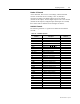
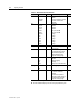
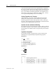
Table 4.3 – Available Channels
Channel Description
Available for
waveform
IL1, IL2, IL3 Phase current Yes
I’L1, I’L2, I’L3 Phase current Yes
Io1, Io2 Measured residual current Yes
f Frequency –
IoCalc Phasor sum Io = (IL1+IL2+IL3)/3 –
I’oCalc Phasor sum Io = (I’L1+I’L2+I’L3)/3 –
I1, I’1 Positive sequence current –
I2, I’2 Negative sequence current –
I2/I1, I’2/I’1 Relative current unbalance –
I2/In, I’2/I’n Current unbalance [xI
GN
] –
IL Average (IL1 + IL2 + IL3)/3 –
I’L Average (I’L1 + I’L2 + I’L3)/3 –
DO Digital outputs Yes
DI Digital inputs Yes
THDIL1 Total harmonic distortion of IL1 –
THDI’L1 Total harmonic distortion of I’L1 –
THDIL2 Total harmonic distortion of IL2 –
THDI’L2 Total harmonic distortion of I’L2 –
THDIL3 Total harmonic distortion of IL3 –
THDI’L3 Total harmonic distortion of I’L3 –
IL1RMS IL1 RMS for average sampling –
IL2RMS IL2 RMS for average sampling –
IL3RMS IL3 RMS for average sampling –
ILmin
I’Lmin
ILmax
I’Lmax
ΔIL1,ΔIL2,ΔIL3
IL1w,IL2w,IL3w
I’L1w,I’L2w,I’L3w