
Manual

Protection Functions 3-23
865-UM001A-EN-P – July 2009
Ip =
Preload current,
nP
IkI ××= θ (If
temperature rise is 120%
2.1=θ ). This
parameter is the memory of the algorithm
and corresponds to the actual temperature
rise.
k = Overload factor (Maximum continuous
current), i.e. service factor. (Setting value)
kΘ
= Ambient temperature factor (Permitted
current due to tamb). See Figure 3.14
I
MODE
= The rated current (I
N
or I
MOT
)
τ
C
= Relay cooling time constant (Setting value)
Time Constant for Cooling Situation
If the transformer's fan is stopped, the cooling will be slower than
with an active fan. Therefore there is a coefficient cΘ for thermal
constant available to be used as cooling time constant, when current
is less than 0.3xI
N
.
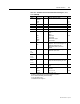
Heat Capacitance, Service Factor and Ambient Temperature
The trip level is determined by the maximum allowed continuous
current I
MAX
corresponding to the 100 % temperature rise Θ
TRIP
i.e.
the heat capacitance of the transformer. I
MAX
depends of the given
service factor k and ambient temperature Θ
AMB
and settings I
MAX40
and I
MAX70
according the following equation.
NMAX
IkkI ⋅⋅=
Θ
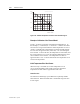
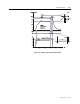
The value of ambient temperature compensation factor kΘ depends
on the ambient temperature Θ
AMB
and settings I
MAX40
and I
MAX70
. See
Figure 3.14. Ambient temperature is not in use when kΘ = 1. This
is true when
IMAX40 is 1.0
Samb is “n/a” (no ambient temperature sensor)
TAMB is +40 °C.