
Manual

3-22 Protection Functions
865-UM001A-EN-P – July 2009
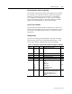
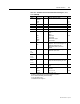
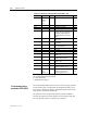
Recorded Values of the Latest Eight Faults
Detailed information is available on the eight latest earth faults: Time
stamp, fault current, elapsed delay and setting group.
Table 3.13 – Parameters of the Undirectional Earth Fault Stages
(8 latest faults) I
0
>>, I
0
>>>, I
0
>>>> (50N/51N)
Parameter Value Unit Description
yyyy-mm-dd Time stamp of the recording, date
hh:mm:ss.ms Time stamp, time of day
Flt pu Maximum earth fault current
EDly % Elapsed time of the operating time setting.
100% = trip
SetGrp
1
2
Active setting group during the fault
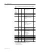
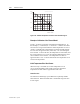
The thermal overload function protects the transformer against
excessive temperatures.
Thermal model
The temperature is calculated using rms values of phase currents and
a thermal model according IEC 60255-8. The rms value is calculated
using harmonic components up to the 15
th
.
Trip time:
22
2
2
ln
aI
II
t
P
−
−
⋅= τ
Alarm:
alarmIkka
e
⋅⋅Θ⋅=
mod
(Alarm 60% = 0.6)
Trip:
e
Ikka
mod
⋅Θ⋅=
Release time:
22
2
ln
Ia
I
Ct
P
−
⋅⋅=
τ
τ
Trip release:
n
Ika ××= 95.0
Start release:
alarmIka
n
×××= 95.0
(Alarm 60% = 0.6)
T = Operation time
τ
= Thermal time constant tau (Setting value)
ln = Natural logarithm function
I = Measured rms phase current (the max. value
of three phase currents)
Thermal Overload
Protection T> (49)