
Manual

Protection Functions 3-19
865-UM001A-EN-P – July 2009
Inverse Operation Time (I
0
> stage only)
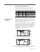
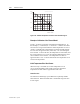
Inverse delay means that the operation time depends on the amount
the measured current exceeds the pick-up setting. The bigger the
fault current is the faster will be the operation. Accomplished
inverse delays are available for the I
0
> stage. The inverse delay
types are described in Chapter 2. The relay will show a scaleable
graph of the configured delay on the local panel display.
Inverse Time Limitation
The maximum measured secondary residual current is 10xI
0N
and
maximum measured phase current is 50xI
N
. This limits the scope of
inverse curves with high pick-up settings. See Chapter 2 for more
information.
Setting Groups
There are two settings groups available for each stage. Switching
between setting groups can be controlled by digital inputs, virtual
inputs (mimic display, communication, logic) and manually.
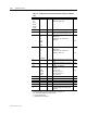
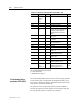
Table 3.11 – Parameters of the Undirectional Earth Fault Stage I
0
> (50N/51N)
Parameter Value Unit Description Note
Status -
Blocked
Start
Trip
Current status of the stage
F
F
TripTime s Estimated time to trip
SCntr Cumulative start counter Clr
TCntr Cumulative trip counter Clr
SetGrp 1 or 2 Active setting group Set
SGrpDI
-
DIx
VIx
LEDx
VOx
Digital signal to select the active setting
group
None
Digital input
Virtual input
LED indicator signal
Virtual output
Set
Force Off
On
Force flag for status forcing for test
purposes. This is a common flag for all
stages and output relays, too.
Automatically reset by a 5-minute
timeout.
Set