
Manual

3-16 Protection Functions
865-UM001A-EN-P – July 2009
0
1
10
100
1000
2
20
200
2000
5
50
500
20
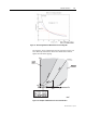
Negative sequence current I (%)
2
CurrentUnbalanceChar
Operation time (s)
40 60 80 100
K =1s
1
K = 50 s
1
K =2%
2
K =2%
2
K = 40 %
2
K = 40 %
2
K = 70 %
2
K = 70 %
2
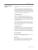
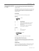
Figure 3.11 – Inverse operation delay of current unbalance stage I
2
>
The longest delay is limited to 1000 seconds (=16min 40s).
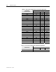
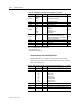
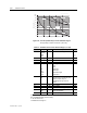
Table 3.9 – Parameters of the Current Unbalance Stage I
2
>, I’
2
> (46)
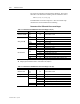
Parameter Value Unit Description Note
Status -
Blocked
Start
Trip
Current status of the stage
F
F
SCntr Cumulative start counter C
TCntr Cumulative trip counter C
SetGrp 1 or 2 Active setting group Set
SGrpDI
-
DIx
VIx
LEDx
VOx
Digital signal to select the active setting
group
None
Digital input
Virtual input
LED indicator signal
Virtual output
Set
Force Off
On
Force flag for status forcing for test
purposes. This is a common flag for all
stages and output relays, too.
Automatically reset by a 5-minute
timeout.
Set
I2/In %In The supervised value.
I2> %In Pick-up setting Set
t> s Definite operation time (Type=DT) Set
Type DT
INV
Definite time
Inverse time (Equation)
Set
K1 s Delay multiplier (Type =INV) Set
For details of setting ranges see “Protection Stages” in Chapter 10.
Set = An editable parameter (password needed)
C = Can be cleared to zero
F = Editable when force flag is on