
Manual

3-14 Protection Functions
865-UM001A-EN-P – July 2009
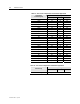
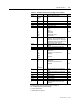
Table 2.7 – Parameters of the Overcurrent Stages I>>, I’>> (50/51)
Parameter Value Unit Description Note
Status
-
Blocked
Start
Trip
Current status of the stage
F
F
SCntr Cumulative start counter C
TCntr Cumulative trip counter C
SetGrp 1 or 2 Active setting group Set
SGrpDI
-
DIx
VIx
LEDx
VOx
Digital signal to select the active setting group
None
Digital input
Virtual input
LED indicator signal
Virtual output
Set
Force
Off
On
Force flag for status forcing for test
purposes. This is a common flag for all
stages and output relays, too. Automatically
reset by a 5-minute timeout.
Set
ILmax A The supervised value. Max. of IL1, IL2 and IL3
I>>, I>>> A Pick-up value scaled to primary value
I>>, I>>> xIn Pick-up setting Set
t>>, t>>> s Definite operation time Set
For details of setting ranges see “Protection Stages” in Chapter 10.
Set = An editable parameter (password needed)
C = Can be cleared to zero
F = Editable when force flag is on
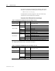
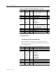
Recorded Values of the Latest Eight Faults
Detailed information is available on the eight latest faults: Time
stamp, fault type, fault current, load current before the fault, elapsed
delay and setting group.
Table 2.8 – Recorded Values of the Overcurrent Stages (8 latest faults) I>, I>>, I>>> (50/51)
Parameter Value Unit Description
yyyy-mm-dd Time stamp of the recording, date
hh:mm:ss.ms Time stamp, time of day
Type
1-N
2-N
3-N
1-2
2-3
3-1
1-2-3
Fault type
Ground fault
Ground fault
Ground fault
Two phase fault
Two phase fault
Two phase fault
Three phase fault
Flt xIgn Maximum fault current
Load xIgn 1 s average phase currents before the fault
EDly % Elapsed time of the operating time setting. 100% = trip
SetGrp 1
2
Active setting group during fault