
Manual

3-10 Protection Functions
865-UM001A-EN-P – July 2009
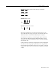
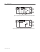
The stage also includes second harmonics blocking. The second
harmonic is calculated from winding currents. Harmonic ratio is:
100 x I
f2_Winding
/ I
f1_Winding
[%]
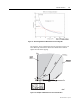
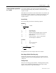
Fast differential overcurrent stage ΔI>> does not include slope
characteristics and second harmonics blocking.
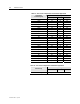
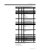
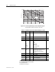
Parameters of the Differential Overcurrent Stages
Table 3.4 – Parameters of the Differential Overcurrent Stages ΔI> (87)
Parameter Value/unit
Measured values
ΔL1
ΔL2
ΔL3
xIn Current difference value
ΔI> %ln Setting value
Slope1 % Slope 1 setting
Ibias2 xIn Bias current start of slope 2
Slope2 % Slope 2 setting
Harm2> On/Off 2. harmonic blocking enable/disable
Setting values
Harm2> % 2. harmonic block limit
TCntr Cumulative trip counter
1-N, 2-N, 3-N Fault type/single-phase fault e.g.: 1-N = fault on phase L1
1-2, 2-3, 1-3 Fault type/two-phase fault e.g.: 2-3 = fault between L2 and L3
Type
1-2-3 Fault type/three-phase fault
ΔFlt xIn Max. value of fault differential current as compared to I
n
Bias xIn Value of bias current of faulted phase as compared to I
n
Recorded values
Load xIn 1 s mean value of pre-fault phase currents IL1…IL3
Measurement ranges are described under “Measuring Circuitry” in Chapter 10.
Setting ranges are described in Table 10.15 and Table 10.16, Chapter 10.
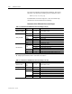
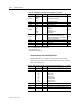
Table 3.5 – Parameters of the Differential Overcurrent Stages ΔI>> (87)
Parameter Value/unit
Measured values
ΔL1
ΔL2
ΔL3
xIn Current difference value
Setting values ΔI>> xIn Setting value
TCntr Cumulative trip counter
1-N, 2-N, 3-N Fault type/single-phase fault e.g.: 1-N = fault on phase L1
1-2, 2-3, 1-3 Fault type/two-phase fault e.g.: 2-3 = fault between L2 and L3
Type
1-2-3 Fault type/three-phase fault
ΔFlt xIn Max. value of fault differential current as compared to I
n
Recorded values
Load xIn 1 s mean value of pre-fault phase currents IL1…IL3