
Manual

Protection Functions 3-7
865-UM001A-EN-P – July 2009
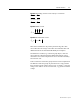
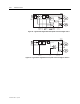
Equation 2: Winding currents in star side, Dy11 connection
33
22
11
''
''
''
LWL
LWL
LWL
II
II
II
=
=
=
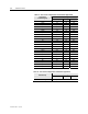
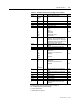
Equation 3: Bias current
2
'
WW
b
II
I
+
=
Equation 4: Differential current
WW
d
III '+=
Bias current calculation is only used in protection stage ΔI>. Bias
current describes the average current flow in transformer. Bias and
differential currents are calculated individually for each phase.
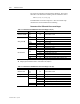
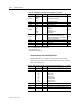
If transformer is earthed, e.g. connection group Dyn11, then zero
current must be compensated before differential and bias current
calculation. Zero current compensation can be selected individually
for IL and I’L side.
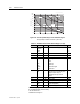
Table 3.2 describes connection group and zero current compensation
for different connection groups. If protection area is only generator
then connection group setting is always Yy0, see Table 3.3. Also the
settings of Un and U’n are set to be the same, e.g. generator nominal
voltage.