
Manual


2-8 Local Panel User Interface
865-UM001A-EN-P – July 2009
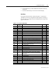
Table 2.2 – List of the Local Main Menu (cont.)
Main menu
Number of
menus
Description ANSI code Note
T> 3 Thermal overload stage 49 4
Io> 5 1st earth fault stage 50N/51N 4
Io>> 3 2nd earth fault stage 50N/51N 4
Io>>> 3 3rd earth fault stage 50N/51N 4
Io>>>> 3 4th earth fault stage 50N/51N 4
Prg1 3 1st programmable stage 4
Prg2 3 2nd programmable stage 4
Prg3 3 3rd programmable stage 4
Prg4 3 4th programmable stage 4
Prg5 3 5th programmable stage 4
Prg6 3 6th programmable stage 4
Prg7 3 7th programmable stage 4
Prg8 3 8th programmable stage 4
CBFP 3 Circuit breaker failure protection 50BF 4
CBWE 4 Circuit breaker wearing supervision 4
CTSV 1 CT supervisor 4
CT’SV 1 CT’ supervisor 4
ArcI> 4 Optional arc protection stage for phase-to-phase faults and
delayed light signal.
50ARC 4
ArcIo> 3 Optional arc protection stage for earth faults. Current input = I01 50NARC 4
ArcIo2> 3 Optional arc protection stage for earth faults. Current input = I02 50NARC 4
OBJ 11 Object definitions 5
Lgic 2 Status and counters of user's logic 1
CONF 10+2 Device setup, scaling etc. 6
Bus 13 Serial port and protocol configuration 7
Diag 6 Device selfdiagnosis
NOTES:
1. Configuration is done with SetPointPS.
2. Recording files are read with SetPointPS.
3. The menu is visible only if protocol ”External IO” is selected for one of the serial ports.
Serial ports are configured in menu ”Bus”.
4. The menu is visible only if the stage is enabled.
5. Objects are circuit breakers, disconnectors, etc. Their position or status can be displayed
and controlled in the interactive mimic display.
6. There are two extra menus, which are visible only if the access level ”operator” or
”configurator” has been opened with the corresponding password.
7. Detailed protocol configuration is done with SetPointPS.
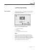
Local Panel Operations
(cont.)