
Manual

Connections 9-7
865-UM001A-EN-P – July 2009
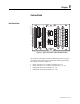
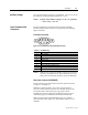
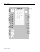
X4 Rear Panel Connector (Local RS232 and Extension RS485 ports)
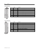
Table 9.3 – Rear Panel Connector Signals
Rear panel port (LOCAL) Pin Signal
X4 1 No connection
X4 2 Rx in, RS232 local
X4 3 Tx out, RS232 local
X4 4 DTR out (+8 V)
X4 5 GND
X4 6 No connection
X4 7 B RS485 extension port
X4 8 A+ RS485 extension port
X4 9 No connection
NOTE: In the Allen-Bradley relays, a positive RS485 voltage from
A+ to B corresponds to bit value “1”. In the X4 connector
the RS485 extension port is not galvanically isolated.
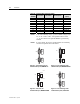
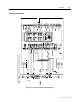
1 2 3 4
Figure 9.7 – Dip Switches in RS-485 and Optic Fiber Options
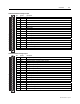
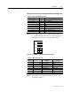
Table 9.4 – DIP Switch Functions
Dip switch
number
Switch Position
Function
RS-485
Function
Fibre optics
1 Left 2-wire connection Echo off
1 Right 4-wire connection Echo on
2 Left 2-wire connection Light on in idle state
2 Right 4-wire connection Light off in idle state
3 Left Termination On Not applicable
3 Right Termination Off Not applicable
4 Left Termination On Not applicable
4 Right Termination Off Not applicable
NOTE: The internal 2-wire RS485 port in X4 connector is not
galvanically isolated.