
Manual

9-6 Connections
865-UM001A-EN-P – July 2009
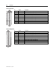
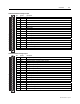
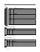
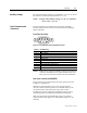
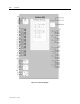
Table 9.2 – Communication Connector Options
Port
(REMOTE)
Pin/ Terminal TTL (Default) RS-485 (Option)
Profibus DP
(Option)
X5 1 reserved Signal Ground
X5 2 Tx out /TTL Receiver
X5 3 Rx in /TTL Receiver + RxD/TxD +/P
X5 4 RTS out /TTL Transmitter RTS
X5 5 Transmitter + GND
X5 6 +5V
X5 7 GND
X5 8 RxD/TxD -/N
X5 9 +8V out
NOTE: In the Allen-Bradley relays, a positive RS485 voltage from
Tx+ to Tx– or Rx+ to Rx– corresponds to the bit value
“1”. In X5 connector the optional RS485 is galvanically
isolated.
NOTE: In 2-wire mode, the receiver and transmitter are internally
connected in parallel. See Table below.
LOCAL
(RS-232)
X4
1
2
3
4
5
6
7
8
9
X5
REMOTE
(TTL)
6
7
8
9
1
2
3
4
5
X45
LOCAL
(RS-232)
REMOTE
(RS485)
1
2
3
4
5
6
7
8
9
123
4
1
2
3
4
5
X5
X4
RS485
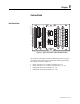
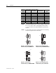
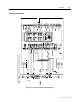
Figure 9.3 – Pin numbering of rear
communication ports, REMOTE TTL
Figure 9.4 – Pin numbering of rear
communication ports, REMOTE RS-485
1
2
3
4
5
6
7
8
9
LOCAL
(RS-232)
REMOTE
(Fibre)
123
4
Fibre RX
Fibre TX
Remote fibre
X5
X4
LOCAL
(RS-232)
X4
1
2
3
4
5
6
7
8
9
X5
ProfibusDP
6
7
8
9
1
2
3
4
5
ProfibusDP
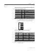
Figure 9.5 – Picture of rear
communication port, REMOTE FIBRE
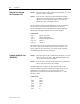
Figure 9.6 – Pin numbering of rear
communication ports, Profibus DP