
Manual


6-2 Control Functions
865-UM001A-EN-P – July 2009
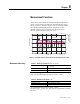
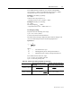
Digital Inputs There are 6 digital inputs available for control purposes. The
polarity – normal open (NO) / normal closed (NC – and a delay can
be configured according the application. The signals are available for
the output matrix, block matrix, user's programmable logic etc.
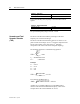
The contacts connected to digital inputs DI1 ... DI6 must be dry
(potential free). These inputs use the common internal 48 Vdc
wetting voltage from terminal X3:1, only.
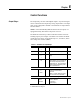
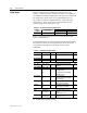
Table 6.2 – Contact Connection to Digital Inputs
Wetting voltage
Common
input
Input group
On Off
X7:7 X7: 1-6 (DI 7-12)
≥18 V
DC
or ≥50 V
AC
≤10 V
DC
or ≤5 V
AC
NOTE: These digital inputs must not be connected parallel with
inputs of another device.
Label and description texts can be edited with SetPointPS according
the application. Labels are the short parameter names used on the
local panel and descriptions are the longer names used by
SetPointPS.
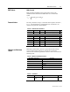
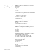
Table 6.3 – Parameters of Digital Inputs
Parameter Value Unit Description Set
DI1 ... DI6 0
1
Status of digital input
DI COUNTERS
DI1 ... DI6 0 ... 65535 Cumulative active edge counter (Set)
DELAYS FOR DIGITAL INPUTS
DI1 ... DI6 0.00 ... 60.00 s Definite delay for both on and off
transitions
Set
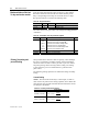
CONFIGURATION DI1 ... DI6
Inverted no
yes
For normal open contacts (NO).
Active edge is 0⇒1
For normal closed contacts (NC)
Active edge is 1⇒0
Set
Alarm display no
yes
No pop-up display
Alarm pop-up display is activated
at active DI edge
Set
On event On
Off
Active edge event enabled
Active edge event disabled
Set
Off event On
Off
Inactive edge event enabled
Inactive edge event disabled
Set
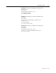
NAMES for DIGITAL INPUTS (editable with SetPointPS only)
Label String of max.
10 characters
Short name for DIs on the local
display
Default is "DIn", n=1...6
Set
Description String of max.
32 characters
Long name for DIs. Default is
"Digital input n", n=1...6
Set
Set = An editable parameter (password needed)