
Manual


Chapter 5
865-UM001A-EN-P – July 2009
Measurement Functions
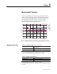
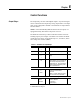
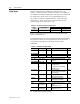
All the direct measurements are based on fundamental frequency
values. (The exceptions are frequency and instantaneous current
for arc protection.) The figure shows a current waveform and the
corresponding fundamental frequency component, second
harmonic and rms value in a special case, when the current
deviates significantly from a pure sine wave.
0.00 0.05 0.10 0.15 0.20 0.25 0.30
Time (s)
Current (PU)
-10
-5
0
5
10
rms
IL2
f1
f2
Load = 0%
InrushCurrentLoad0
Relative 2nd
harmonic f2/f1 (%)
0
50
100
f2/f1 (%)
Figure 5.1 – Example of various current values of a transformer inrush current
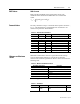
Table 5.1 – Phase Current Inputs I
L1
, I
L2
, I
L3
, I’
L1
, I’
L2
, I’
L3
Measuring range 0 – 250 A (5A)
0 – 50 A (1A)
Inaccuracy I ≤ 7.5 A
0.5 % of value or 15 mA
I > 7.5 A 3 % of value
The rated input I
N
is 5A or 1A. It is specified in the order code of the
relay. The specified frequency range is 45 Hz – 65 Hz.
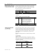
Table 5.2 – Residual Current Inputs I
01
, I
02
Measuring range 0 – 5 xI
n
Inaccuracy I ≤ 1.5 xI
n
0.3 % of value or 0.2 % of I
n
I > 1.5 xI
n
3 % of value
The specified frequency range is 45 Hz – 65 Hz.
The rated input I
n
is 5A or 1A. This must be specified when ordering
the relay.
Measurement Accuracy