865 Differential Protection Relay For Motor, Transformer and Generator Differential Protection Bulletin 865, Series A User Manual
Important User Information Solid-state equipment has operational characteristics differing from those of electromechanical equipment. Safety Guidelines for the Application, Installation and Maintenance of Solid-State Controls (Publication SGI-1.1 available from your local Rockwell Automation sales office or online at http://literature.rockwellautomation.com) describes some important differences between solid-state equipment and hard-wired electromechanical devices.
Table of Contents Chapter 1 Overview Chapter 2 Local Panel User Interface Chapter 3 Protection Functions Introduction ............................................................................. 1-1 Main Relay Features ................................................................1-1 User Interface ...........................................................................1-3 Operating Safety ..................................................................... 1-3 Relay Front Panel ..............
ii Table of Contents Chapter 3 Protection Functions (cont.) 865-UM001A-EN-P – July 2009 Retardation Time .............................................................. 3-3 Reset Time (Release Time) .............................................. 3-4 Hysteresis or Dead Band .................................................. 3-5 Differential Overcurrent Protection ΔI> (87) ......................... 3-6 Parameters of the Differential Overcurrent Stages ......... 3-10 Overcurrent Protection I> (50/51) .....
Table of Contents Chapter 3 Chapter 4 Protection Functions (cont.) Supporting Functions Inverse Time Operation ........................................................ Stage Specific Inverse Delay .......................................... Operation Modes ............................................................ Local Panel Graph .......................................................... Inverse Time Setting Error Signal .................................. Limitation .................................
iv Table of Contents Chapter 5 Measurement Functions Measurement Accuracy ...........................................................5-1 Harmonics and Total Harmonic Distortion (THD) ................. RMS Values ............................................................................ RMS Currents ................................................................... Demand Values ....................................................................... Maximum and Maximum Values ..........................
Table of Contents Chapter 8 Applications Restricted Earth Fault Protection .............................................8-1 Restricted Earth Fault Protection for a Transformer With Neutral Connection ................................................. 8-2 CT Requirements ............................................................. 8-2 Calculating the Stabilizing Resistance RS, VDR Value, and Actual Sensitivity ................................................ 8-3 Value of Stabilizing Resistor RS ..........
vi Table of Contents Chapter 10 Technical Data Connections .......................................................................... 10-1 Measuring Circuitry ....................................................... 10-1 Auxiliary Voltage ........................................................... 10-1 Digital Inputs .................................................................. 10-2 Trip Contacts .................................................................. 10-2 Alarm Contacts ..................
Chapter 1 Overview Introduction The Allen-Bradley 865 differential protection system includes all the essential protection functions needed to protect transformers for distribution networks of utilities, industry, power plants and offshore applications as well as motor and generator differential protection. Further, the device includes several programmable functions, such as thermal and circuit breaker protection and communication protocols for various protection and communication situations.
1-2 Overview Main Features (cont.) • • • • • • • • Freely configurable interlocking schemes with basic logic functions Recording of events and fault values into an event register from which the data can be read via a keypad and a local HMI or by means of a PC based SetPointPS user interface Latest events and indications are in non-volatile memory.
Overview 1-3 User Interface The relay can be controlled in three ways: • Locally with the push-buttons on the relay front panel • Locally using a PC connected to the serial port on the front panel or on the rear panel of the relay (both cannot be used simultaneously) • Via remote control over the remote control port on the relay rear panel. Operating Safety ATTENTION The terminals on the rear panel of the relay may carry dangerous voltages, even if the auxiliary voltage is switched off.
1-4 Overview 865-UM001A-EN-P – July 2009
Chapter 2 Local Panel User Interface Relay Front Panel The figure below shows, as an example, the front panel of the Allen-Bradley 865 relay and the location of the user interface elements used for local control. Figure 2.1 – Front Panel of Allen-Bradley 865 Relay 1. 2. 3. 4. LCD dot matrix display Keypad LED indicators RS 232 serial communication port for PC Display The relay is provided with a backlit 128x64 LCD dot matrix display.
2-2 Local Panel User Interface 4 3 Q1 Q4 2 K0006 Q0 Q3 L 5 50.02 Hz 6 AR: 1 Q9 1 7 Figure 2.2 – Sections of the LCD Matrix Display 1. 2. 3. 4. 5. 6. 7. Freely configurable single-line diagram Five controllable objects Status for six independent objects Bay identification Local/Remote selection Auto-reclose on/off selection (if applicable) Freely selectable measurement values (max. six values) Figure 2.3 – Sections of the LCD Matrix Display 1. 2. 3. 4. 5. 6.
Local Panel User Interface 2-3 Backlight Control Display backlight can be switched on with a digital input, virtual input or virtual output. LOCALPANEL CONF/Display backlight ctrl setting is used for selecting trigger input for backlight control. When the selected input activates (rising edge), display backlight is set on for 60 minutes. Menu Navigation and Pointers 1. Use the arrow keys UP and DOWN to move up and down in the main menu, that is, on the left-hand side of the display.
2-4 Local Panel User Interface 4. Keys for selecting submenus [selecting a digit in a numerical value] (LEFT/RIGHT) 5. Additional information key (INFO) NOTE: The term, which is used for the buttons in this manual, is inside the rounded brackets. Operation Indicators The relay is provided with eight LED indicators: Power Error Com Alarm Trip A B C Figure 2.5 – Operation Indicators of the Relay Table 2.
Local Panel User Interface 2-5 Resetting Latched Indicators and Output Relays All the indicators and output relays can be given a latching function in the configuration. There are several ways to reset latched indicators and relays: • From the alarm list, move back to the initial display by pushing the CANCEL key for approx. 3 s. Then reset the latched indicators and output relays by pushing the ENTER key. • Acknowledge each event in the alarm list one by one by pushing the ENTER key equivalent times.
2-6 Local Panel User Interface Local Panel Operations (cont.) 5. Pushing the UP or DOWN key in any position of a sub-menu, when it is not selected, brings you directly one step up or down in the main menu. The active main menu selection is indicated with black background color. The possible navigating directions in the menu are shown in the upper-left corner by means of black triangular symbols. Figure 2-6 – Example of Scroll Indication Figure 2.
Local Panel User Interface 2-7 6. Push the INFO key to obtain additional information about any menu item. 7. Push the CANCEL key to revert to the normal display. Main Menu The general menu structure is shown in Figure 2.7. The menu is dependent on the user's configuration and the options according to the order code. For example only the enabled protection stages will appear in the menu. Table 2.
2-8 Local Panel User Interface Local Panel Operations (cont.) Table 2.2 – List of the Local Main Menu (cont.
Local Panel User Interface 2-9 Menu Structure of Protection Functions The general structure of all protection function menus is similar although the details do differ from stage to stage. As an example the details of the second overcurrent stage I>> menus are shown below: FIRST MENU OF I>> 50/51 STAGE I>> STATUS ExDO Prot I> I>> Iv> Ij> Status SCntr TCntr SetGrp SGrpDI Force 50/51 5 2 1 Off Figure 2.8 – First Menu of I>>50/51 Stage This is the status, start and trip counter and setting group menu.
2-10 Local Panel User Interface Local Panel Operations (cont.) SECOND MENU OF I>> 50/51 STAGE Stage ExDI ExDO Prot I>> CBWE OBJ I>> SET 50/51 setting group 1 ILmax 403A Status I>> 1013A I>> 2.50xIgn t>> 0.60s Figure 2.9 – Second Menu (next to the right) of I>>50/51 Stage This is the main setting menu. The content is: 865-UM001A-EN-P – July 2009 • Stage setting group 1 – These are the group 1 setting values. The other setting group can be seen by pressing push buttons ENTER and then RIGHT or LEFT.
Local Panel User Interface 2-11 THIRD MENU OF I>> 50/51 STAGE FAULT ExDI ExDO Prot I>> CBWE OBJ I>> LOG 50/51 LOG 1 2006-09-14 12:25:10.288 Type 1-2 Flt 2.86xIgn Load 0.99xIgn EDly 81% SetGrp 1 Figure 2.10 – Third and Last Menu (next to the right) of I>>50/51 Stage This is the menu for registered values by the I>> stage. Fault logs are explained under “Fault Logs” on page 2-13. • FAULT LOG 1 – This is the latest of the eight available logs.
2-12 Local Panel User Interface Local Panel Operations (cont.) Setting Groups Most of the protection functions of the relay have two setting groups. These groups are useful for example when the network topology is changed frequently. The active group can be changed by a digital input, through remote communication or locally by using the local panel. The active setting group of each protection function can be selected separately. Figure 2.
Local Panel User Interface 2-13 Fault Logs All the protection functions include fault logs. The fault log of a function can register up to eight different faults with time stamp information, fault values etc. Each function has its own logs (See Figure 2.13). Figure 2.13 – Example of Fault Log To see the values of, for example, log two, press the ENTER key to select the current log (log one). The current log number is then indicated in the down-left corner of the display (See Figure 2.
2-14 Local Panel User Interface Local Panel Operations (cont.) Operating Levels The relay has three operating levels: User level, Operator level and Configurator level. The purpose of the access levels is to prevent accidental change of relay configurations, parameters or settings. USER level Use: Opening: Closing: Possible to read e.g.
Local Panel User Interface 2-15 Opening Access 1. Push the INFO key and the ENTER key on the front panel. ENTER PASSWORD *** 0 Figure 2.15 – Opening the Access Level 2. Enter the password needed for the desired level: the password can contain four digits. The digits are supplied one by one by first moving to the position of the digit using the RIGHT key and then setting the desired digit value using the UP key. 3. Push the ENTER key.
2-16 Local Panel User Interface Operating Measures Control Functions The default display of the local panel is a single-line diagram including relay identification, Local/Remote indication, Auto-reclose on/off selection and selected analogue measurement values. Please note that the operator password must be active in order to be able to control the objects. Please refer to ‘Opening Access’ on page 2-15. Toggling Local/Remote Control 1. Push the ENTER key. The previously activated object starts to blink.
Local Panel User Interface 2-17 Measured Data The measured values can be read from the main menus and their submenus. Furthermore, any measurement value in the following table can be displayed on the main view next to the single line diagram. Up to six measurements can be shown. Table 2.
2-18 Local Panel User Interface Operating measures (cont.) Figure 2.16 – Example of Harmonics Bar Display Reading Event Register The event register can be read from the EVNT submenu: 1. Push the RIGHT key once. 2. The EVENT LIST appears. The display contains a list of all the events that have been configured to be included in the event register. Figure 2.17 – Example of an Event Register 3. Scroll through the event list with the UP and DOWN keys. 4. Exit the event list by pushing the LEFT key.
Local Panel User Interface 2-19 Forced Control (Force) In some menus it is possible to switch a signal on and off by using a force function. This feature can be used, for instance, for testing a certain function. The force function can be activated as follows: 1. Move to the setting state of the desired function, for example DO (see section “Configuration and Parameter Setting”). 2. Select the Force function (the background color of the force text is black). Figure 2.18 – Selecting Force Function 3.
2-20 Local Panel User Interface Configuration and Parameter Setting The minimum procedure to configure a relay is: 1. Open the access level "Configurator". The default password for configurator access level is 2. 2. Set the rated values in menu [CONF] including at least current transformers and a protected transformer rating. Also the date and time settings are in this same main menu. 3. Enable the needed protection functions and disable the rest of the protection functions in main menu [Prot]. 4.
Local Panel User Interface 2-21 Parameter Setting 1. Move to the setting state of the desired menu (for example CONF/CURRENT SCALING) by pushing the ENTER key. The Pick text appears in the upper-left part of the display. 2. Enter the password associated with the configuration level by pushing the INFO key and then using the arrow keys and the ENTER key (default value is 0002). For more information about the access levels, please refer to section “Operating Levels”. 3.
2-22 Local Panel User Interface Configuration and Parameter Setting (cont.) Setting Range Limits If the given parameter setting values are out-of-range values, a fault message will be shown when the setting is confirmed with the ENTER key. Adjust the setting to be within the allowed range. Figure 2.21 – Example of a Fault Message The allowed setting range is shown in the display in the setting mode. To view the range, push the INFO key. Push the CANCEL key to return to the setting mode. Figure 2.
Local Panel User Interface 2-23 Disturbance Recorder Menu DR Via the submenus of the disturbance recorder menu the following functions and features can be read and set: DISTURBANCE RECORDER • • • • • • Recording mode (Mode) Sample rate (Rate) Recording time (Time) Pre trig time (PreTrig) Manual trigger (MnlTrig) Count of ready records (ReadyRe) REC.
2-24 Local Panel User Interface Configuration and Parameter Setting (cont.
Local Panel User Interface 2-25 Configuration Menu CONF The following functions and features can be read and set via the submenus of the configuration menu: DEVICE SETUP • • Bit rate for the command line interface in ports X4 and the front panel. The front panel is always using this setting. If SPABUS is selected for the rear panel local port X4, the bit rate is according SPABUS settings.
2-26 Local Panel User Interface Configuration and Parameter Setting (cont.
Local Panel User Interface 2-27 Protocol Menu Bus There are three communication ports in the rear panel. In addition there is a connector in the front panel overruling the local port in the rear panel. REMOTE PORT X5 • • Communication protocol for remote port X5 [Protocol]. Message counter [Msg#]. This can be used to verify that the device is receiving messages. • Communication error counter [Errors]. • Communication time-out error counter [Tout]. • Information of bit rate/data bits/parity/stop bits.
2-28 Local Panel User Interface Configuration and Parameter Setting (cont.) EXTENSION PORT X4 (pins 7, 8 and 5) • • • • • Communication protocol for extension port X4 [Protocol]. Message counter [Msg#]. This can be used to verify that the device is receiving messages. Communication error counter [Errors]. Communication time-out error counter [Tout]. Information of bit rate/data bits/parity/stop bits. This value is not directly editable. Editing is done in the appropriate protocol setting menus.
Local Panel User Interface 2-29 PROFIBUS Only one instance of this protocol is possible. • [Mode] • Bit rate [bit/s]. Use 2400 bps. This parameter is the bit rate between the main CPU and the Profibus ASIC. The actual Profibus bit rate is automatically set by the Profibus master and can be up to 12 Mbit/s. • Event numbering style [Emode]. • Size of the Profibus Tx buffer [InBuf]. • Size of the Profibus Rx buffer [OutBuf].
2-30 Local Panel User Interface Configuration and Parameter Setting (cont.) DEVICENET The optional plug on DeviceNet Communication Module provides the following features: Node address and network data rate is programmable through the front panel of the 865 relay. Alternatively, the configuration settings can be accomplished over the DeviceNet network, utilizing a network configuration tool such as RSNetWorx for DeviceNet.
Local Panel User Interface Bay 2-31 0 L 0A 0.000A 0kW 0Kvar Figure 2.23 – Single Line Diagram Blocking and Interlocking Configuration The configuration of the blockings and interlockings is done with the SetPointPS software. Any start or trip signal can be used for blocking the operation of any protection stage. Furthermore, the interlocking between objects can be configured in the same blocking matrix of the SetPointPS software. For more information, please refer to the SetPointPS manual.
2-32 Local Panel User Interface 865-UM001A-EN-P – July 2009
Chapter 3 Protection Functions Each protection stage can independently be enabled or disabled according to the requirements of the intended application. Maximum Number of Protection Stages in one application Protection Functions The device limits the maximum number of enabled stages to about 30, depending on the type of the stages. For more information, please see the configuration instructions in Chapter 2 in the first part of this manual. Table 3.
3-2 Protection Functions Forcing Start or Trip Condition for Testing The status of a protection stage can be one of the followings: • • Ok = ‘–‘ The stage is not detecting any fault. Blocked • • Start The stage is detecting a fault but blocked by some reason. The stage is counting the operation delay. Trip The stage has tripped and the fault is still on. The blocking reason may be an active signal via the block matrix from other stages, the programmable logic or any digital input.
Protection Functions 3-3 Blocking Any protection function, except arc protection, can be blocked with internal and external signals using the block matrix (Chapter 5). Internal signals are for example logic outputs and start and trip signals from other stages and external signals are for example digital and virtual inputs. Some protection stages have also inbuilt blocking functions. For example under-frequency protection has inbuilt under-voltage blocking to avoid tripping when the voltage is off.
3-4 Protection Functions Definition of retardation time: If the delay setting would be slightly shorter, an unselective trip might occur (the dash line pulse). For example when there is a big fault in an outgoing feeder, it might start i.e. pick-up both the incoming and outgoing feeder relay. However the fault must be cleared by the outgoing feeder relay and the incoming feeder relay must not trip.
Protection Functions 3-5 Hysteresis or Dead Band hysteresis When comparing a measured value against a pick-up value, some amount of hysteresis is needed to avoid oscillation near equilibrium situation. With zero hysteresis any noise in the measured signal or any noise in the measurement itself would cause unwanted oscillation between fault-on and fault-off situations. Hysteresis_GT PICK UP LEVEL > PICK UP Figure 3.3 – Behavior of a greater than comparator.
3-6 Protection Functions Differential Overcurrent Protection ΔI> (87) The differential overcurrent protection comprises two separately adjustable stages, stage ΔI> and stage ΔI>>. The differential protection is based on winding currents difference between IL and I’L side. In transformer applications the current calculation depends on transformer connection group. E.g. in Yy0 connection measured currents are also winding currents, see Figure 3.5.
Protection Functions 3-7 Equation 2: Winding currents in star side, Dy11 connection I ' L1W = I ' L1 I ' L 2W = I ' L 2 I ' L 3W = I ' L 3 Equation 3: Bias current Ib = IW + I ' W 2 Equation 4: Differential current I d = IW + I ' W Bias current calculation is only used in protection stage ΔI>. Bias current describes the average current flow in transformer. Bias and differential currents are calculated individually for each phase. If transformer is earthed, e.g.
3-8 Protection Functions Table 3.
Protection Functions 3-9 Figure 3.7 – Block Diagram of the Differential Overcurrent Stage ΔI> The stage ΔI> can be configured to operate as shown in Figure 3.8. This dual slope characteristic allows more differential current at higher currents before tripping. Figure 3.
3-10 Protection Functions The stage also includes second harmonics blocking. The second harmonic is calculated from winding currents. Harmonic ratio is: 100 x If2_Winding / If1_Winding [%] Fast differential overcurrent stage ΔI>> does not include slope characteristics and second harmonics blocking. Parameters of the Differential Overcurrent Stages Table 3.
Protection Functions Overcurrent Protection I> (50/51) 3-11 Overcurrent protection is used against short circuit faults and heavy overloads. The overcurrent function measures the fundamental frequency component of the phase currents. The protection is sensitive for the highest of the three phase currents. Whenever this value exceeds the user's pick-up setting of a particular stage, this stage picks up and a start signal is issued.
3-12 Protection Functions Figure 3.9 – Typical block diagram of the three-phase overcurrent stage I> and I’> Figure 3.
Protection Functions 3-13 Table 2.
3-14 Protection Functions Table 2.
Protection Functions 3-15 Current unbalance protection The current unbalance stage protects against unbalanced phase currents and single phasing. The protection is based on the negative I2>, I’2> (46) sequence current. Both definite time and inverse time characteristics are available. The inverse delay is based on Equation 5. Only the base frequency components of the phase currents are used to calculate the negative sequence value I2. Inverse Delay The inverse delay is based on the following equation.
3-16 Protection Functions CurrentUnbalanceChar 2000 1000 Operation time (s) K2 = 40 % K2 = 2 % 500 K2 = 70 % 200 K1 = 50 s 100 50 K2 = 2 % 20 K2 = 40 % K2 = 70 % 10 5 K1 = 1 s 2 1 0 20 40 60 Negative sequence current I2 (%) 80 100 Figure 3.11 – Inverse operation delay of current unbalance stage I2> The longest delay is limited to 1000 seconds (=16min 40s). Table 3.
Protection Functions 3-17 Recorded Values of the Latest Eight Faults Detailed information is available on the eight latest faults: Time stamp, unbalance current, elapsed delay and setting group. Table 3.10 – Parameters of the Current Unbalance Stage (8 latest faults) I2>, I’2> (46) Parameter Value yyyy-mm-dd hh:mm:ss.
3-18 Protection Functions Figure 3.12 shows a functional block diagram of the I0> earth overcurrent stage with definite time and inverse time operation time. Figure 3.13 shows a functional block diagram of the I0>>, I0>>> and I0>>>> earth fault stages with definite time operation delay.
Protection Functions 3-19 Inverse Operation Time (I0> stage only) Inverse delay means that the operation time depends on the amount the measured current exceeds the pick-up setting. The bigger the fault current is the faster will be the operation. Accomplished inverse delays are available for the I0> stage. The inverse delay types are described in Chapter 2. The relay will show a scaleable graph of the configured delay on the local panel display.
3-20 Protection Functions Table 3.11 – Parameters of the Undirectional Earth Fault Stage I0> (50N/51N) (cont.) Parameter Io Io2 IoCalc IoPeak Io2Peak I’oCalc Io> Io> Value Unit pu A pu Curve DT IEC IEEE IEEE2 RI PrgN Type s k> Input Intrmt Dly20x Dly4x Dly2x Dly1x A, B, C, D, E Pick-up value scaled to primary value Pick-up setting relative to the parameter "Input" and the corresponding CT value Delay curve family: Definite time Inverse time. See “Inverse Time Operation”. Delay type.
Protection Functions 3-21 Table 3.
3-22 Protection Functions Recorded Values of the Latest Eight Faults Detailed information is available on the eight latest earth faults: Time stamp, fault current, elapsed delay and setting group. Table 3.13 – Parameters of the Undirectional Earth Fault Stages (8 latest faults) I0>>, I0>>>, I0>>>> (50N/51N) Parameter Value yyyy-mm-dd hh:mm:ss.
Protection Functions Ip = Preload current, I P = θ × k × I n (If k = kΘ = IMODE = = temperature rise is 120% θ = 1.2 ). This parameter is the memory of the algorithm and corresponds to the actual temperature rise. Overload factor (Maximum continuous current), i.e. service factor. (Setting value) Ambient temperature factor (Permitted current due to tamb). See Figure 3.
3-24 Protection Functions kQ AmbientTemperatureCompensation 1.2 1.0 0.8 IMAX40 IMAX70 0.6 10 20 30 40 50 60 70 80 QAMB (°C) Figure 3.14 – Ambient Temperature Correction of the Overload Stage T> Example of a Behavior of the Thermal Model Figure 3.15 shows an example of the thermal model behavior. In this example τ = 30 minutes, k = 1.06 and kτ = 1 and the current has been zero for a long time and thus the initial temperature rise is 0 %. At time = 50 minutes the current changes to 0.
Protection Functions 3-25 Figure 3.
3-26 Protection Functions Table 3.14 – Parameters of the Thermal Overload Stage T> (49) Parameter Value Status Blocked Start Trip hh:mm:ss Time SCntr TCntr Force Unit F F % MaxRMS Note Current status of the stage Off On T Description Arms Estimated time to trip Cumulative start counter Cumulative trip counter Force flag for status forcing for test purposes. This is a common flag for all stages and output relays, too. Automatically reset by a 5-minute timeout. Calculated temperature rise.
Protection Functions 3-27 If this time is longer than the operating time of the CBFP stage, the CBFP stage activates another output relay, which will remain activated until the primary trip relay resets. The CBFP stage is supervising all the protection stages using the same selected trip relay, since it supervises the control signal of this relay. See Chapter 5 for details about the output matrix and the trip relays. Table 3.
3-28 Protection Functions Arc fault protection (50ARC/50NARC) (optional) NOTE: This protection function needs optional hardware in slot X6. More details of the hardware can be found under “Optional TwoChannel Arc Protection Card” in Chapter 9, and “Arc Protection Interface (Option)” in Chapter 10. Arc protection is used for fast arc protection. The function is based on simultaneous light and current measurement. Special arc sensors are used to measure the light of an arc.
Protection Functions 3-29 Binary Output The binary output (BO) on the arc option card (see Chapter 8) can be used to give the light indication signal or any other signal or signals to another relay's binary input to build selective arc protection systems. Selection of the BO connected signal(s) is done with the output matrix (See Chapter 5). BO is an internally wetted 48 Vdc signal for BI of other Allen-Bradley relays or dedicated arc protection devices by Allen-Bradley.
3-30 Protection Functions Table 3.17 – Parameters of Arc Protection Stages Arcl>, Arcl’>, Arcl01A, Arcl02> (50 ARC / 50N ARC) (cont.
Protection Functions Programmable Stages (99) 3-31 For special applications the user can built his own protection stages by selecting the supervised signal and the comparison mode. The following parameters are available: • Priority If operation times less than 60 milliseconds are needed select 10 ms. For operation times under one second 20 ms is recommended. For longer operation times and THD signals 100 ms is recommended. • Link The name of the supervised signal (see table below).
3-32 Protection Functions Table 3.19 – Parameters of the Programmable Stages PrgN (99) Parameter Status SCntr TCntr SetGrp SGrpDI Force Link Value Unit Description Blocked Start Trip Note Current status of the stage Cumulative start counter Cumulative trip counter Active setting group Digital signal to select the active setting group None Digital input Virtual input LED indicator signal Virtual output 1 or 2 DIx VIx LEDx VOx Off On Force flag for status forcing for test purposes.
Protection Functions Inverse Time Operation 3-33 The inverse time operation – i.e. inverse delay minimum time (IDMT) type of operation – is available for several protection functions. The common principle, formula and graphic representations of the available inverse delay types are described in this chapter. Inverse delay means that the operation time depends on the measured real time process values during a fault.
3-34 Protection Functions Inverse Time Setting Error Signal If there are any errors in the inverse delay configuration the appropriate protection stage will use definite time delay. There is a signal ‘Setting Error’ available in output matrix, which indicates three different situations: 1. Settings are currently changed with SetPointPS or local panel, and there is temporarily an illegal combination of curve/delay/points.
Protection Functions 3-35 Table 3.21 – Maximum Secondary Scaling Settings Maximum secondary scaled setting enabling inverse delay times up to 20x setting RATED INPUT Order code IL Allen-Bradley 865-1_ Allen-Bradley 865-3_ Allen-Bradley 865-4_ Allen-Bradley 865-5_ Allen-Bradley 865-_A Allen-Bradley 865-_B Allen-Bradley 865-_C Allen-Bradley 865-_D I’L 1 1 5 5 I01 I02 1 5 1 5 5 5 1 1 IL1, IL2, IL3 & I0Calc I’L1, I’L2, I’L3 & I’0Calc 2.5 A 2.5 A 12.5 A 12.5 A 2.5 A 12.5 A 2.5 A 12.
3-36 Protection Functions Table 3.
Protection Functions 3-37 Table 3.23 – Constants for IEC Inverse Delay Equation Delay type NI EI VI LTI Normal inverse Extremely inverse Very inverse Long time inverse Parameter A 0.14 80 13.5 120 B 0.02 2 1 1 Example for Delay type "Normal inverse (NI) ": k = 0.50 I = 4 pu (constant current) Ipickup = 2 pu A = 0.14 B = 0.02 t= 0.50 ⋅ 0.14 ⎛4⎞ ⎜ ⎟ ⎝2⎠ 0.02 = 5.0 −1 The operation time in this example will be 5 seconds. The same result can be read from Figure 3.16. Figure 3.
3-38 Protection Functions Figure 3.18 – IEC Very Inverse Delay Figure 3.19 – IEC Long Time Inverse Delay IEEE/ANSI Inverse Time Operation There are three different delay types according IEEE Std C37.1121996 (MI, VI, EI) and many de facto versions according Table 3.24. The IEEE standard defines inverse delay for both trip and release operations. However, in the Allen-Bradley relay only the trip time is inverse according the standard but the release time is constant.
Protection Functions 3-39 Table 3.24 – Constants for IEEE/ASI Inverse Delay Equation Delay type LTI LTVI LTEI MI VI EI STI STEI Long time inverse Long time very inverse Long time extremely inverse Moderately inverse Very inverse Extremely inverse Short time inverse Short time extremely inverse A 0.086 28.55 64.07 0.0515 19.61 28.2 0.16758 1.281 Parameter B 0.185 0.712 0.250 0.1140 0.491 0.1217 0.11858 0.005 C 0.02 2 2 0.02 2 2 0.02 2 Example for Delay type "Moderately inverse (MI)": k = 0.
3-40 Protection Functions 865-UM001A-EN-P – July 2009 Figure 3.22 – ANSI/IEEE Long Time Extremely Inverse Delay Figure 3.23 – ANSI/IEEE Moderately Inverse Delay Figure 3.24 – ANSI/IEEE Short Time Inverse Delay Figure 3.
Protection Functions 3-41 IEEE2 Inverse Time Operation Before the year 1996 and ANSI standard C37.112, microprocessor relays were using equations approximating the behavior of various induction disc type relays. A quite popular approximation is Equation 8, which in the 865 is called IEEE2. Another name could be IAC, because the old General Electric IAC relays have been modeled using the same equation. There are four different delay types according Table 3.25.
3-42 Protection Functions Example for Delay type "Moderately inverse (MI)": k = 0.50 I = 4 pu Ipickup = 2 pu A = 0.1735 B = 0.6791 C = 0.8 D = -0.08 E = 0.127 ⎡ ⎤ ⎥ ⎢ − 0.08 0.127 ⎥ 0.6791 ⎢ + + = 0.38 t = 0.5 ⋅ 0.1735 + 2 3 ⎢ ⎥ ⎛4 ⎞ ⎛4 4 ⎞ ⎛ ⎞ ⎜ − 0 .8 ⎟ ⎜ − 0 .8 ⎟ ⎜ − 0 .8 ⎟ ⎥ ⎢ ⎝2 ⎠ ⎝2 ⎠ ⎝2 ⎠ ⎦ ⎣ The operation time in this example will be 0.38 seconds. The same result can be read from Figure 3.26. Figure 3.26 – IEEE2 Moderately Inverse Delay 865-UM001A-EN-P – July 2009 Figure 3.
Protection Functions Figure 3.28 – IEEE2 Very Inverse Delay 3-43 Figure 3.29 – IEEE2 Extremely Inverse Delay RI and RXIDG type Inverse Time Operation These two inverse delay types have their origin in old ASEA (ABB) earth fault relays. The operation delay of types RI and RXIDG depends on the measured value and other parameters according Equation 9 and Equation 10. Actually these equations can only be used to draw graphs or when the measured value I is constant during the fault.
3-44 Protection Functions Equation 10 – RXIDG t RXIDG = 5.8 − 1.35 ln t k I Ipickup = = = = I k I pickup Operation delay in seconds User’s multiplier Measured value User’s pick up setting Example for Delay type RI : k = 0.50 I = 4 pu Ipickup = 2 pu t RI = 0.5 = 2.3 0.236 0.339 − ⎛4⎞ ⎜ ⎟ ⎝2⎠ The operation time in this example will be 2.3 seconds. The same result can be read from Figure 3.30. Example for Delay type RXIDG: k = 0.50 I = 4 pu 2 pu Ipickup = t RXIDG = 5.8 − 1.35 ln 4 = 3.9 0.
Protection Functions Figure 3.30 –Inverse Delay of type RI 3-45 Figure 3.31 – Inverse Delay of type RXIDG Parameter Setting using IEC, IEEE and IEEE2 Equations This mode is activated by setting delay type to ‘Parameters’, and then editing the delay function constants, i.e. the parameters A ... E. The idea is to use the standard equations with one’s own constants instead of the standardized constants as in the previous chapter. Example for GE-IAC51 delay type inverse: k = 0.
3-46 Protection Functions Inverse Time Setting Error Signal The inverse time setting error signal will become active, if interpolation with the given parameters is not possible. See Chapter 2 for more details. Limitations The minimum definite time delay start latest, when the measured value is twenty times the setting. However, there are limitations at high setting values due to the measurement range. See Chapter 2 for more details.
Protection Functions 3-47 Inverse Time Setting Error Signal The inverse time setting error signal will be activated, if interpolation with the given points fails. See section “Inverse Time Operation” for more details. Limitations The minimum definite time delay start latest, when the measured value is twenty times the setting. However, there are limitations at high setting values due to the measurement range. See section “Inverse Time Operation” in Chapter 2 for more details.
3-48 Protection Functions 865-UM001A-EN-P – July 2009
Chapter 4 Supporting Functions Event Log Event log is a buffer of event codes and time stamps including date and time. For example each start-on, start-off, trip-on or trip-off of any protection stage has a unique event number code. Such a code and the corresponding time stamp are called an event. As an example of information included with a typical event an overvoltage trip event of the first 59 stage U> is shown in the following table. Table 4.
4-2 Supporting Functions Event Buffer Overflow The normal procedure is to poll events from the device all the time. If this is not done, the event buffer will eventually overflow. On the local screen this is indicated with string "OVF" after the event code. Table 4.
Supporting Functions 4-3 Number of Channels At the maximum, there can be 12 recordings, and the maximum selection of channels in one recording is also 12 (limited in waveform recording). The digital inputs reserve one channel (includes all the inputs). Also the digital outputs reserve one channel (includes all the outputs). If digital inputs and outputs are recorded, there will be still 10 channels left for analogue waveforms. Available Channels The following channels i.e.
4-4 Supporting Functions Table 4.
Supporting Functions 4-5 Table 4.4 – Disturbance Recorder Parameters (cont.) Parameter AddCh ClrCh (Ch) Value IL1, IL2, IL3 I’L1, I’L2, I’L3 Io1, Io2 f IoCalc I1, I2, I2/I1 I2/In, IoCalc I’1, I’2, I’2/I’1 I’2/I’n, I’oCalc IL, I’L DO, DI THDIL1 THDIL2 THDIL3 IL1RMS IL2RMS IL3RMS ILmin, ILmax I’Lmin I’Lmax ΔIL1, ΔIL2, ΔIL3 IL1w, IL2w, IL3w I’L1w, I’L2w, I’L3w – Clear Unit Description Note Add one channel. Maximum simultaneous number of channels is 12.
4-6 Supporting Functions Table 4.5 – Setting Parameters of CT, CT’ Supervisor – CTSV ( ) Parameter Imax> Imin< t> CT on CT off Value 0.0 … 10.0 0.0 … 10.0 0.02 … 600.0 On; Off On; Off Unit Default Description xIn xIn s - 2.0 0.2 0.10 On On Upper setting for CT supervisor Lower setting for CT supervisor Operation delay CT supervisor on event CT supervisor off event Table 4.
Supporting Functions 4-7 The points 4...8 are not needed for the CB in Figure 4.1. Thus they are set to 100 kA and one operation in the table to be discarded by the algorithm. Number of permitted operations 100000 10000 1000 100 50 20 10 100 200 500 1000 10000 Breaked current (A) 100000 CBWEARcharacteristics Figure 4.1 – An example of circuit breaker wearing characteristic graph Table 4.
4-8 Supporting Functions Any actual interrupted current will be logarithmically weighted for the two given alarm current levels and the number of operations left at the alarm points is decreased accordingly. When the "operations left" i.e. the number of remaining operations, goes under the given alarm limit, an alarm signal is issued to the output matrix. Also an event is generated depending on the event enabling.
Supporting Functions 4-9 Example of the Logarithmic Interpolation Alarm 2 current is set to 6 kA. What is the maximum number of operations according Table 4.7. The current 6 kA lies between points 2 and 3 in the table. That gives value for the index k. Using: k Ck Ck+1 Ik+1 Ik = = = = = 2 10000 80 31 kA 1.25 kA and the Equation 4.2 and Equation 4.3, the relay calculates 10000 80 = 1.5038 n= 31000 ln 1250 a = 10000 ⋅ 12501.5038 = 454 ⋅ 10 6 ln Using Equation 4.
4-10 Supporting Functions Equation 4.4 Δ= C AlarmMax C Δ L1 = Δ L 2 = 945 =3 313 Thus Alarm2 counters for phases L1 and L2 are decremented by 3. In phase L1 the currents is less than the alarm limit current 6 kA. For such currents the decrement is one. Δ L3 = 1 Table 4.
Supporting Functions System Clock and Synchronization 4-11 The internal clock of the relay is used to time stamp events and disturbance recordings. The system clock should be externally synchronized to get comparable event time stamps for all the relays in the system. The synchronizing is based on the difference of the internal time and the synchronizing message or pulse. This deviation is filtered and the internal time is corrected softly towards a zero deviation.
4-12 Supporting Functions Example 1: If there has been no external sync and the relay's clock is leading sixty-one seconds a week and the parameter AAIntv has been zero, the parameters are set as AvDrft = Lead 604.8 AAIntv = = 9.9 s 61 With these parameter values the system clock corrects itself with –1 ms every 9.9 seconds which equals 61.091 s/week. Example 2: If there is no external sync and the relay's clock has been lagging five seconds in nine days and the AAIntv has been 9.
Supporting Functions System Clock Parameters 4-13 Table 4.9 – System Clock Parameters Parameter Value Unit Date Time Style Y–d–m d.m.y m/d/y SyncDI TZone DST – DI1 ... DI6 –12.00 ... +14.00 No Yes SySrc MsgCnt Internal DI SNTP SpaBus ModBus ProfibusDP IEC-103 DNP3 0 ... 65535, 0 ... etc. Dev ±32767 SyOS ±10000.000 s AAIntv ±10000 s AvDrft Lead Lag FilDev ±125 ms ms Description Note Current date Current time Date format Year-Month-Day Day.Month.
4-14 Supporting Functions Running Hour Counter This function calculates the total active time of the selected digital input, virtual I/O or output matrix output signal. The resolution is ten seconds. Table 4.10 – Running Hour Counter Parameters Value Unit Runh Parameter 0 ... 876000 h 0 ... 3599 0 ... 65535 Stop Run s Starts Status DI – DI1 ...DI6, VI1...VI4, LedAl, LedTr, LedA, LedB, LedC, LedDR VO1...
Supporting Functions 4-15 Figure 4.2 – Timer Output Sequence in Different Modes The user can force any timer, which is in use, on or off. The forcing is done by writing a new status value. No forcing flag is needed as in forcing i.e. the output relays. The forced time is valid until the next forcing or until the next reversing timed act from the timer itself. The status of each timer is stored in non-volatile memory when the auxiliary power is switched off.
4-16 Supporting Functions Combined Overcurrent Status This function is collecting faults, fault types and registered fault currents of all enabled overcurrent stages. Table 4.12 – Line Fault Parameters Parameter Value IFltLas LINE ALARM AlrL1 AlrL2 0 AlrL3 1 OCs 0 1 Unit xIN On Off LxAlarmOff On Off OCAlarm On Off OCAlarmOff On Off IncFltEvnt On Off LINE FAULT FltL1 FltL2 FltL3 Oct 0 ... 65535 0 1 0 1 Note (Set) Start (=alarm) status for each phase.
Supporting Functions 4-17 Table 4.12 – Line Fault Parameters (cont.) Parameter Value Unit LxTrip On Off LxTripOff On Off OCTrip On Off OCTripOff On Off IncFltEvnt On Off ClrDly 0 ...
4-18 Supporting Functions 865-UM001A-EN-P – July 2009
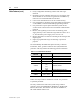
Chapter 5 Measurement Functions Load = 0% 10 Current (PU) rms 5 f2/f1 (%) f1 100 50 f2 0 0 Relative 2nd harmonic f2/f1 (%) All the direct measurements are based on fundamental frequency values. (The exceptions are frequency and instantaneous current for arc protection.) The figure shows a current waveform and the corresponding fundamental frequency component, second harmonic and rms value in a special case, when the current deviates significantly from a pure sine wave. -5 IL2 -10 0.00 0.
5-2 Measurement Functions Table 5.3 – Frequency Measuring range Inaccuracy 16 Hz – 75 Hz 10 mHz In the Allen-Bradley 865, frequency is measured from current signals. Table 5.4 – THD and Harmonics Inaccuracy I 0.1 PU Update rate 2 % units Once a second The specified frequency range is 45 Hz – 65 Hz. Harmonics and Total Harmonic Distortion (THD) The device calculates the THDs as percentage of the base frequency for currents and voltages.
Measurement Functions RMS Values 5-3 RMS Currents Relay calculates the RMS value of each phase current. The minimum and the maximum of RMS values are recorded and stored. 2 2 I rms = I f 1 + I f 2 + ... + I f 15 Demand Values 2 The relay calculates average i.e. demand values of phase currents IL1, IL2, IL3. The demand time is configurable from 10 minutes to 30 minutes with parameter "Demand time". Table 5.5 – Demand Value Parameters Parameter Value Time 10 ...
5-4 Measurement Functions Maximum Values of the last 31 days and twelve months Some maximum and minimum values of the last 31 days and the last twelve months are stored in the non-volatile memory of the relay. Corresponding time stamps are stored for the last 31 days. The registered values are listed in the following table. Table 5.
Measurement Functions 5-5 For residual currents to inputs I01 or I02 use the corresponding CTPRI and CTSEC values. For earth fault stages using I0Calc signals use the phase current CT values for CTPRI and CTSEC. Example 1: Secondary to primary. CT = 500/5 Current to the relay's input is 4 A. ⇒ Primary current is IPRI = 4x500/5 = 400 A Example 2: Primary to secondary.
5-6 Measurement Functions Primary, Secondary and per unit Scaling (cont.) Example 1: Secondary to per unit and percent for phase currents excluding ArcI>. CTPRI = 150/1 CTSEC = 800/5 SN = 25 MVA UN = 110 kV U'N = 21 kV Current injected to the relay's primary side input is 175 mA and 859 mA for the secondary side input. The rated current on HV and LV side will be IN = 25 MVA/ (√3 x 110 kV) = 131.2 A I'N = 25 MVA/ (√3 x 21 kV) = 687.3 A ⇒ Per unit currents are IPU = 0.175x150/(1x131.2) = 0.
Measurement Functions 5-7 Example 6: Per unit to secondary for residual current. Input is I01 or I02. CT0 = 50/1 The relay setting is 0.03 pu = 3 %. ⇒ Secondary current is ISEC = 0.03x1 = 30 mA Example 7: Secondary to per unit for residual current. Input is I0Calc. CT = 750/5 Currents injected to the relay's IL1 input is 0.5 A. IL2 = IL3 = 0. ⇒ Per unit current is IPU = 0.5/5 = 0.1 pu = 10 % Example 8: Per unit to secondary for residual current. Input is I0Calc. CT = 750/5 The relay setting is 0.
5-8 Measurement Functions 865-UM001A-EN-P – July 2009
Chapter 6 Control Functions Output Relays The output relays are also called digital outputs. Any internal signal can be connected to the output relays using output matrix. An output relay can be configured as latched or non-latched. See output matrix for more details. NOTE: If the Allen-Bradley Bulletin 865 has the mA option, it is equipped with only three alarm relays from A1 to A3. The difference between trip contacts and alarm contacts is the DC breaking capacity. See Chapter 9 for details.
6-2 Control Functions Digital Inputs There are 6 digital inputs available for control purposes. The polarity – normal open (NO) / normal closed (NC – and a delay can be configured according the application. The signals are available for the output matrix, block matrix, user's programmable logic etc. The contacts connected to digital inputs DI1 ... DI6 must be dry (potential free). These inputs use the common internal 48 Vdc wetting voltage from terminal X3:1, only. Table 6.
Control Functions 6-3 Table 6.4 – Summary of Digital Inputs Virtual Inputs and Outputs DI 1 2 3 4 5 6 Terminal X3:1 X3:2 X3:3 X3:4 X3:5 X3:6 X3:7 19 X6:1…2 Operating voltage 48VDC supply for DI1…6 Internal 48VDC External 18…865 VDC 50…250 VAC Availability Allen-Bradley 865 ARC card with 2 DIs There are four virtual inputs and six virtual outputs. The four virtual inputs acts like normal digital inputs.
6-4 Control Functions Output Matrix By means of the output matrix, the output signals of the various protection stages, digital inputs, logic outputs and other internal signals can be connected to the output relays, front panel indicators, virtual outputs etc. There are two LED indicators named "Alarm" and "Trip" on the front panel. Furthermore there are three general purpose LED indicators – "A", "B" and "C" available for customer-specific indications.
Control Functions Blocking Matrix 6-5 By means of a blocking matrix, the operation of any protection stage can be blocked. The blocking signal can originate from the digital inputs DI1 to DI6, or it can be a start or trip signal from a protection stage or an output signal from the user's programmable logic. In the block matrix Figure 6.2 an active blocking is indicated with a black dot (•) in the crossing point of a blocking signal and the signal to be blocked. Figure 6.
6-6 Control Functions Object States Each object has the following states: Table 6.6 – Object States Setting Value Undefined (00) Open Close Undefined (11) Object state Description Actual state of the object Basic Settings for Controllable Objects Each controllable object has the following settings: Table 6.
Control Functions 6-7 Settings for Read-only Objects Each read-only object has the following settings: Table 6.9 – Settings for Read-only Objects Setting Value DI for ‘obj open’ Description DI for ‘obj close’ None, any digital input, virtual input or virtual output Object timeout 0.02 … 600 s Open information Close information Timeout for state changes If changing states takes longer than the time defined by “Object timeout” setting, object fails and “Object failure” matrix signal is set.
6-8 Control Functions Logic Functions The relay supports customer-defined programmable logic for Boolean signals. The logic is designed by using the SetPointPS setting tool and downloaded to the relay. Functions available are: AND OR XOR NOT COUNTERs RS & D flip-flops Maximum number of outputs is 20. Maximum number of input gates is 31. An input gate can include any number of inputs. For detailed information, please refer to the SetPointPS manual (857-PM001A-EN-P).
Chapter 7 Communications Communication Ports The relay has three communication ports as standard. There are three communication ports in the rear panel. The Ethernet port is optional. The X4 connector includes two ports: local port and extension port. The front panel RS-232 port will shut off the local port on the rear panel when a programming cable (#857-VX003-3) is inserted.
7-2 Communications Local Port X4 The local port has two connectors: On the front panel X4 the rear panel (D9S pins 2, 3 and 5) Only one can be used at a time. NOTE: The extension port is locating in the same X4 connector. NOTE: When the 857-VX003-3 cable is inserted to the front panel connector it activates the front panel port and disables the rear panel local port by connecting the DTR pin 6 and DSR pin 4 together. See Figure 7.1.
Communications 7-3 Table 7.1 – Local Port X4 Parameters Parameter Value Protocol None SpaBus ProfibusDP ModbusSla ModbusTCPs IEC-103 ExternalIO DNP3 DeviceNet Msg# 0 ... 232–1 Errors 0 ... 216–1 Tout 0 ... 216–1 speed/DPS Unit Description Note Protocol selection for the rear panel local port. Command line interface for SetPointPS SPA-bus (slave) Profibus DB (slave) Modbus RTU slave Modbus TCP slave IEC-60870-5-103 (slave) Modbus RTU master for external I/Omodules DNP 3.
7-4 Communications Remote Port X5 Physical Interface The physical interface of this port depends on the communications type. See Figure 7.1, Chapter 12 and the table below. The TTL interface is for external converters and converter cables only. It is not suitable for direct connection to distances more than one meter. Table 7.2 – Physical Interface and Connector Types of Remote Port X5 with Various Options. TTL (A) is the default.
Communications 7-5 Table 7.3 – Remote Port X5 Parameters Parameter Value Protocol None SPA-bus ProfibusDP ModbusSla ModbusTCPs IEC-103 ExternalIO DNP3 DeviceNet Msg# 0 ... 232–1 Errors 0 ... 216–1 Tout 0 ... 216–1 speed/DPS Debug No Binary ASCII Unit Description Note Protocol selection for remote port – SPA-bus (slave) Profibus DB (slave) Modbus RTU slave Modbus TCP slave IEC-60870-5-103 (slave) Modbus RTU master for external I/Omodules DNP 3.
7-6 Communications Extension Port X4 This is a non-isolated RS-485 port for external I/O devices. The port is located in the same rear panel D9S connector X4 as the local port, but pins (7, 8, 5) are used instead of the standard RS-232 pins (2, 3, 5) used by the local port. See Figure 7.1. Table 7.4 – Extension Port X4 Parameters Parameter Value Protocol None SPA-bus ProfibusDP ModbusSla ModbusTCPs IEC-103 ExternalIO Msg# DNP3 0 ... 232–1 Errors 0 ... 216–1 Tout 0 ...
Communications 7-7 Optional Inbuilt Ethernet Port This is an optional inbuilt Ethernet port for SetPointPS and Modbus TCP and other communication protocols using TCP/IP. See Figure 7.1 The IP address, net mask, gateway, name server and NTP server are common with the internal Ethernet port setting in section “IEC 60870-5-l01”, page 7.15. Table 7.5 – Optional Inbuilt Ethernet Port Parameters Parameter Value Protocol None SPA-bus ModbusTCPs IEC-103 ExternalIO Port IpAddr DNP3 Default = 502 n.n.n.
7-8 Communications Communication Protocols These protocols enable the transfer of the following type of data: • events • status information • measurements • control commands. • clock synchronizing • Settings (SPA-bus and embedded SPA-bus only) PC Communication PC communication is using an Allen-Bradley specified command line interface. The SetPointPS program can communicate using the local RS-232 port or using TCP/IP and Ethernet interface.
Communications 7-9 Profibus DP The Profibus DP protocol is widely used in industry worldwide. An external or internal Profibus module is required. Device profile "Continuous Mode" In this mode the device is sending a configured set of data parameters continuously to the Profibus DP master. The benefit of this mode is the speed and easy access to the data in the Profibus master. The drawback is the maximum buffer size of 128 bytes, which limits the number of data items transferred to the master.
7-10 Communications Table 7.7 – Profibus DP Parameters Parameter Value Unit Mode bit/s Cont Reqst 2400 bps Emode Channel (Limit60) (NoLimit) InBuf bytes OutBuf bytes Addr 1 – 247 Conv – VE Description Note Profile selection Continuous mode Request mode Communication speed from the main CPU to the Profibus converter. (The actual Profibus bit rate is automatically set by the Profibus master and can be up to 12 Mbit/s.) Event numbering style. Use this for new installations.
Communications 7-11 Table 7.8 – SPA-bus Parameters Parameter Addr Value Unit Description Note Set bps SPA-bus address. Must be unique in the system. Communication speed Event numbering style. Use this for new installations. (The other modes are for compatibility with old systems.
7-12 Communications The device will accept: • ASDU 6: Time synchronization • ASDU 7: Initiation of general interrogation and • ASDU 20: General command The data in a message frame is identified by: • type identification • function type and • information number These are fixed for data items in the compatible range of the protocol, for example, the trip of I> function is identified by: type identification = 1, function type = 160 and information number = 90.
Communications 7-13 Table 7.10 – Parameters for Disturbance Record Reading Parameter ASDU23 Smpls/msg Timeout Fault Value On Off 1–25 10–10000 TagPos Chn ChnPos Fault numbering Faults GridFlts Grid Unit s Description Note Enable record info message Set Record samples in one message Record reading timeout Fault identifier number for IEC-103. Starts + trips of all stages.
7-14 Communications Table 7.11 – DPN 3.
Communications 7-15 Table 7.12 – IEC 60870-5-101 Parameters Parameter Value Unit bps LLAddr LLAddrSize ALAddr ALAddrSize 1200 2400 4800 9600 None Even Odd 1 – 65534 1–2 1 – 65534 1–2 Bytes IOAddrSize 2–3 Bytes COTsize TTFormat 1 Short Full Bytes MeasFormat Scaled Normalized DbandEna No Yes 100 – 10000 bit/s Parity DbandCy bytes ms Description Note Bitrate used for serial communication.
7-16 Communications TCP/IP Modbus TCP uses TCP/IP protocol. Also SetPointPS and SPA-bus and DNP 3.0 communication can be directed via TCP/IP. The IP address, net mask, gateway, name server and NTP server are common with the internal Ethernet port setting. Table 7.13 – TCP/IP Parameters Parameter Value IpAddr n.n.n.n NetMsk Gatew n.n.n.n default = 0.0.0.0 NameSv NTPSvr default = 0.0.0.0 n.n.n.
Chapter 8 Applications Restricted Earth Fault Protection Restricted earth fault (REF) protection is a sensitive way to protect a zone between two measuring points against earth faults. See Figure 8.1. Note: The CT secondaries are wired to cancel each other's currents during through faults and to drive all to the relay when the fault is inside the protected zone. (Saturation of the CTs makes the situation a little more complicated than that.
8-2 Applications Restricted Earth Fault Protection for a Transformer with Neutral Connection Figure 8.2 shows and example where three phase current CTs are connected parallel with each other and then in series with the CT in the neutral point. 865 X1-1 1A X1-2 I L1 X1-3 1A X1-4 I L2 X1-5 1A X1-6 I L3 VDR Note: All the CTs have the same ratio and the nominal secondary current is 1 A.
Applications Calculating the Stabilizing Resistance RS, VDR Value and Actual Sensitivity 8-3 Value of stabilizing resistor RS The voltage VS (Figure 8.1) is: Equation 8.1 VS = I MAXT CTSEC RCT + RW CTPRIM IMAXT CTSEC CTPRI RCT RW Maximum through fault current not to cause an REF trip Nominal secondary current of the CT Nominal primary current of the CT Resistance of CT secondary. Total resistance of wiring, connections etc.
8-4 Applications RW = RS = Total resistance of wiring, connections, relay input etc. Stabilizing resistor according to Equation 8.2. The peak voltage of a saturating CT can be approximated using P. Mathews' formula: Equation 8.4 Vsp = 2 2VKPV P − VKP VKP = VP Knee point voltage of the CT. The secondary voltage at which a 50 % increase of primary current is needed to increase the secondary voltage by 10%.
Applications 8-5 Approximation of peak voltage during inside fault using a non-linear model for a saturating CT (Equation 8.4): Vsp = 2 2 ⋅100(12600 − 100) = 3.2 kV This is a too high value and a VDR must be used to reduce the voltage below 3 kV. A zinc oxide varistor (i.e. VDR, METROSIL) of 1 kV will limit the voltage. Using a 400 J model allows two 20 VA CTs feeding ten times their nominal power during one second before the energy capacity of the varistor is exceeded.
8-6 Applications Equation 8.5 T 1 ( K N iS − i P ) 2 dt ∫ T 0 εC = T KN iS iP IP IP = = = = = ⋅ 100% Cycle time Rated transformation ratio INPrimary/INsecondary Instantaneous secondary current Instantaneous primary current Rms value of primary current NOTE: All current based protection functions of Allen-Bradley relays, except arc protection, thermal protection and 2nd harmonic blocking functions, are using the fundamental frequency component of the measured current.
Applications 8-7 Accuracy limit factor kALF The ratio of the accuracy limit current to the rated primary current. Equation 8.6 K ALF = I AL IN The standard accuracy limit factors are 5, 10, 15, 20 and 30. Marking: Accuracy limit factor is written after the accuracy class. E.g. 10 VA 5P10, 15 VA 10P10, 30 VA 5P20. The actual accuracy limit factor kA depends on the actual burden. Equation 8.
8-8 Applications CT Requirement for Protection When the through current equals and exceeds kAxIN there may be enough secondary differential current to trip a relay although there is no in zone fault. This is because the CTs are unique and they do not behave equally when approaching saturation. To avoid false trips caused by heavy through faults the actual accuracy limit factor kA of the CTs should exceed the relative setting ISET of the non-stabilized differential stage. Equation 8.
Applications 8-9 Formula to solve needed CT burden By replacing the complex power terms with corresponding resistances in equation 8.7, we get Equation 8.9 k A = k ALF RCT + R N RCT + RW + R L where the nominal burden resistance is RN = RCT RW RL SN INCTsec S I N 2 NCT sec = = = = = Winding resistance (See Figure 8.
8-10 Applications CTs on LV side: 500/5 5P10 (Max. Short circuit current is 4400 A = 8.8 x 500 A) Winding resistance RCT = 0.28 Ω (RCT depends on the CT type, INCT and power rating. Let's say that the selected CT type, 500 A and an initial guess of 15 VA yields to 0.28 Ω) Safety factor c = 3. (Transformer differential, Δ.) Differential current setting of the non-stabilized stage ΔI>>: ISET = 9 x IN RL RWHV RWLV = 0.008 ΩTypical burden of an Allen-Bradley relay current input. = 0.
Applications 8-11 Bulletin 865 Protection of a Dyn11 Transformer Figure 8.
Applications Bulletin 865 8-12 Figure 8.
Applications 8-13 Bulletin 865 Protection of a YNd11 Transformer Figure 8.
8-14 Applications Bulletin 865 Protection of Generator and Block Transformer Figure 8.
Applications 8-15 Bulletin 865 Application example of Differential Protection using Allen-Bradley 865 Relay Figure 8.
8-16 Applications Trip Circuit Supervision Trip circuit supervision is used to ensure that the wiring from the protective relay to the circuit breaker is in order. This circuit is most of the time unused, but when the protection relay detects a fault in the network it is too late to notice that the circuit breaker cannot be tripped because of a broken trip circuitry. A digital input of the relay can be used for trip circuit monitoring.
Applications 8-17 +VAUX 865 Digital input trip circuit failure alarm + +48 V 1 DI K1 Trip relay Delay Alarm relay for trip circuit failure A snap in relay module K1: Phoenix Contact EMG 17-REL/KSR-120/21 Au Coil: 96 .. 127 V, 24 kohm Contact material: 5 mm Au (AgPd60) Width: 17.5 mm Assembly: DIN EN 50022 mounting rail relay compartment circuit breaker compartment close control R1 -VAUX OPEN COIL CB -VAUX CLOSE COIL TripCircuitSup200OpenP os Figure 8.
8-18 Applications 865-UM001A-EN-P – July 2009
Chapter 9 Connections Rear Panel View 1 1 2 2 2 3 3 3 4 4 4 5 5 6 6 6 7 7 7 2 I L1 I L2 3 4 I L2 I L3 5 6 I L3 I 01 I 01 7 9 9 I 02 9 10 I 02 10 10 I´L1 11 12 I´L1 I´L2 13 14 I´L2 I´L3 15 16 I´L3 A4 A3 8 11 12 12 13 13 14 A2 14 15 16 17 18 15 16 IF 17 X4 17 18 19 20 18 VYX060A Uaux X5 LOCAL (RS 232) T1 5 I L1 1 8 11 T2 A5 X1 REMOTE (TTL) 1 8 A1 X2 40..265V AC/DC 48V DI1 DI2 DI3 DI4 DI5 DI6 X6 X3 Digital inputs Figure 9.
9-2 Connections Terminal X1 Left Side No: 1 3 5 7 9 11 13 15 17 19 Symbol IL1 IL2 IL3 Io1 Io2 I’L1 I’L2 I’L3 --- Description Phase current IL1 (S1), high voltage side Phase current IL2 (S1), high voltage side Phase current IL3 (S1), high voltage side Residual current Io1 (S1) Residual current Io2 (S1) Phase current I’L1 (S1), low voltage side Phase current I’L2 (S1), low voltage side Phase current I’L3 (S1), low voltage side --- No: 2 4 6 8 10 12 14 16 18 20 Symbol IL1 IL2 IL3 Io1 Io2 I’L1 I’L2 I’L3 -
Connections 9-3 Terminal X2 without the analogue output No: Symbol Description 1 --2 --3 --4 --5 A5 Alarm relay 5 6 A5 Alarm relay 5 7 A4 Alarm relay 4 8 A4 Alarm relay 4 9 --10 A3 COM Alarm relay 3, common connector 11 A3 NC Alarm relay 3, normal closed connector 12 A3 NO Alarm relay 3, normal open connector 13 A2 COM Alarm relay 2, common connector 14 A2 NC Alarm relay 2, normal closed connector 15 A2 NO Alarm relay 2, normal open connector 16 IF COM Internal fault relay, common connector 17 IF NC Inter
9-4 Connections Terminal X3 No: 1 2 3 4 5 6 7 8 9 10 11 12 13 14 15 16 17 18 Symbol +48V DI1 DI2 DI3 DI4 DI5 DI6 -A1 COM A1 NO A1 NC T2 T2 T1 T1 -Uaux Uaux Description Internal wetting voltage for digital inputs 1 – 6 Digital input 1 Digital input 2 Digital input 3 Digital input 4 Digital input 5 Digital input 6 -Alarm relay 1, common connector Alarm relay 1, normal open connector Alarm relay 1, normal closed connector Trip relay 2 Trip relay 2 Trip relay 1 Trip relay 1 -Auxiliary voltage Auxiliary volt
Connections Auxiliary Voltage 9-5 The external auxiliary voltage Uaux (standard 40…865 V ac or dc) for the terminal is connected to the terminals X3: 17-18. NOTE: Polarity of the auxiliary voltage Uaux (24 V ac, option B): – = X3: 17 and + = X3: 18 Serial Communication Connectors The pin assignments of communication connectors including internal communication converters are presented in the following figures and tables. Front Panel Connector Figure 9.
9-6 Connections Table 9.2 – Communication Connector Options Port (REMOTE) X5 X5 X5 X5 X5 X5 X5 X5 X5 Pin/ Terminal 1 2 3 4 5 6 7 8 9 TTL (Default) reserved Tx out /TTL Rx in /TTL RTS out /TTL Profibus DP (Option) RS-485 (Option) Signal Ground Receiver Receiver + Transmitter Transmitter + RxD/TxD +/P RTS GND +5V GND RxD/TxD -/N +8V out NOTE: In the Allen-Bradley relays, a positive RS485 voltage from Tx+ to Tx– or Rx+ to Rx– corresponds to the bit value “1”.
Connections 9-7 X4 Rear Panel Connector (Local RS232 and Extension RS485 ports) Table 9.3 – Rear Panel Connector Signals Rear panel port (LOCAL) X4 X4 X4 X4 X4 X4 X4 X4 X4 Pin 1 2 3 4 5 6 7 8 9 Signal No connection Rx in, RS232 local Tx out, RS232 local DTR out (+8 V) GND No connection B RS485 extension port A+ RS485 extension port No connection NOTE: In the Allen-Bradley relays, a positive RS485 voltage from A+ to B corresponds to bit value “1”.
9-8 Connections Optional Two-Channel Arc Protection Card NOTE: When this option card is installed, the parameter "Arc card type" has value "2Arc+BI/O". NOTE: If the slot X6 is already occupied with the DI19/DI20 digital input card, this option is not available, but there is still one arc sensor channel available. (See ‘Optional Digital I/O Card – DI19/DI20’ below.) The optional arc protection card includes two arc sensor channels. The arc sensors are connected to terminals X6: 4-5 and 6-7.
Connections 9-9 Bulletin 865 Connection Examples Figure 9.
9-10 Connections Figure 9.
Chapter 10 Technical Data Connections Table 10.
10-2 Technical Data Table 10.3 – Digital Inputs Number of inputs Operation time Polarity Inaccuracy: - Operate time Internal operating voltage Current drain when active (max.) Current drain, average value Terminal block: - Phoenix MVSTBW or equivalent 6 0.00 – 60.00 s (step 0.01 s) NO (normal open) or NC (normal closed) ±1% or ±10 ms 48 V dc Approx. 20 mA < 1 mA Max. wire dimension: 2.5 mm2 (13-14 AWG) Table 10.4 – Trip Contacts Number of contacts Rated voltage Continuous carry Make and carry, 0.
Technical Data 10-3 Table 10.6 – Local Serial Communication Port Number of ports Electrical connection Data transfer rate 1 on front and 1 on rear panel RS 232 1200 - 38 400 kb/s Table 10.
10-4 Technical Data Tests and Environmental Conditions Table 10.9 – Disturbance Tests Emission (EN 50081-1) - Conducted (EN 55022B) - Emitted (CISPR 11) Immunity (EN 50082-2) - Static discharge (ESD) - Fast transients (EFT) - Surge - Conducted HF field - Emitted HF field - GSM test 0.15 - 30 MHz 30 - 1 000 MHz EN 61000-4-2, class III 6 kV contact discharge 8 kV air discharge EN 61000-4-4, class III 2 kV, 5/50 ns, 5 kHz, +/EN 61000-4-5, class III 2 kV, 1.2/50 s, common mode 1 kV, 1.
Technical Data 10-5 Table 10.13 – Casing Degree of protection (IEC 60529) Dimensions (W x H x D) Material Weight Colour code IP20 208 x 155 x 225 mm 1 mm steel plate 4.2 kg RAL 7032 (Casing) / RAL 7035 (Back plate) Table 10.14 – Package Dimensions (W x H x D) Weight (Terminal, Package and Manual) Protection Stages 215 x 160 x 275 mm 5.2 kg Differential Protection Table 10.
10-6 Technical Data Non-directional Current Protection Table 10.17 – Overcurrent Stage I>, I’> (50/51) Pick-up current Definite time function: - Operating time IDMT function: - Delay curve family - Curve type - Time multiplier k Start time Reset time Retardation time Reset ratio Transient over-reach, any τ Inaccuracy: - Starting - Operating time at definite time function - Operating time at IDMT function 0.10 – 5.00 x Imode DT 0.08 – 300.00 s (step 0.
Technical Data 10-7 Table 10.19 –Thermal overload stage T> (49) Setting range: Alarm setting range: Time constant Tau: Cooling time coefficient: Max. overload at +40 °C Max. overload at +70 °C Ambient temperature Resetting ratio (Start & trip) Accuracy: - operating time 0.1 – 2.40 x Imot or IN (step 0.01) 60 – 99 % (step 1%) 2 – 180 min (step 1) 1.0 – 10.0 xTau (step 0.1) 70 – 120 %Imot (step 1) 50 – 100 %Imot (step 1) -55 – 125 °C (step 1°) 0.95 ±5% or ±1 s Table 10.
10-8 Technical Data Table 10.21 – Earth fault stage I0> (50N/51N) Input signal Setting range I0> Definite time function: - Operating time IDMT function: - Delay curve family - Curve type - Time multiplier k Start time Reset time Reset ratio Inaccuracy: - Starting - Starting (Peak mode) - Operating time at definite time function - Operating time at IDMT function. I0 ( input X1-7 & 8) I02 ( input X1-9 & 10) I0Calc ( = IL1+IL2+IL3) 0.005 … 8.00 When I0 or I02 0.05 … 20.0 When I0Calc DT 0.08 – 300.
Technical Data 10-9 Circuit-breaker Failure Protection Table 10.23 – Circuit-breaker failure protection CBFP (50BF) Relay to be supervised Definite time function - Operating time Reset time Inaccuracy - Operating time T1-T12 0.1 – 10.0 s (step 0.1 s) <95 ms ±20 ms This is the instantaneous time i.e. the minimum total operational time including the fault detection time and operation time of the trip contacts.
10-10 Technical Data Table 10.25 –Arc protection stage ArcI0> (50AR), option (cont.) Inaccuracy: - Starting - Operating time - Delayed ARC light 10% of the set value ±5 ms ±10 ms Table 10.
Chapter 11 Abbreviations and Symbols ANSI American National Standards Institute. A standardization organization. CB Circuit breaker CBFP Circuit breaker failure protection cosϕ Active power divided by apparent power = P/S. (See power factor PF). Negative sign indicates reverse power. CT Current transformer CTPRI Nominal primary value of current transformer CTSEC Nominal secondary value of current transformer Dead band See hysteresis.
11-2 Abbreviations and Symbols LAN Local area network. Ethernet based network for computers and relays. Latching Output relays and indication LEDs can be latched, which means that they are not released when the control signal is releasing. Releasing of lathed devices is done with a separate action. NTP Network time protocol for LAN and WWW pu Per unit. Depending of the context the per unit refers to any nominal value. For example for overcurrent setting 1 pu = 1xIGN.
Chapter 12 Installation Figure 12.
12-2 Order Information Figure 12.
Medium Voltage Products, 135 Dundas Street, Cambridge, ON, N1R 5X1 Canada, Tel: (1) 519.740.4100, Fax: (1) 519.623.8930, www.ab.com/mvb Publication 865-UM001A-EN-P – July 2009 Copyright © 2009 Rockwell Automation, Inc. All rights reserved.