
Owner's manual
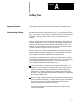

Using Transfer Line Cycles
Chapter 31
31-51
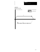
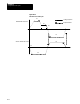
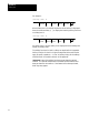
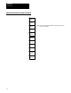
Template 19: Two -Axis Cross Feed Cycle
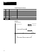
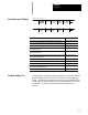
Letter Paramacro Label Description
F
1
500
MAINRAPID FEEDRATE Thevelocity ofthe toolas itapproachesthepart.
X
1
501
MAINFEED START The positionofthe tool as itdrillsinto the part.
F
2
502
MAIN FEEDRATE The velocityof the tool asitdrills intothe part.
X
2
503
MAIN FINAL POSITION The depth ofthetoolatits final positioninthepart.
F
3
504
CROSS FEEDRATE (MAX) The velocityofthetoolasittraversesthe part.
Y
1
505
CROSSFINALPOSITION The final position ofthe tool afterittraverses the part.
X
3
506
MAIN RETURN POSITION The position ofthe tool when itstarted thecycle.
Y
2
507
CROSSRETURN POSITION The position oftheslide when itstarted the cycle.
F
4
508
CROSSRETURN RAPID The velocityoftheslideas itreturns to itsstarting position.
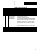
E 509
ADAPTIVE FEED MINIMUM Thisistheminimumfeedrateatwhichthecontrol performsan adaptive feed operation.
The controlwilltrytomaintain thisminimumfeedrate,evenifitmeans increasingthe
adaptive feed torquepercent.Formoreinformationon adaptive feed,refertopage 18-9.
Q 510
ADAPTIVE FEED TORQUE % Thisistheamountofthe selectedservo’scontinuousrated torqueas enteredinAMPby
yoursysteminstaller. Valid ranges are from1 to 150% oftheservo’srated torque.
Refertoyoursysteminstaller’s documentationfordetailson the rated torque ofthe
servos in your system.
Important:Thetorque amountapplied bytheservo isnotthecuttingforce. Itisthe
torque applied bytheservotothe axis. You mustcalculatetheequivalentcutting force
basedon yourmachine dynamics(motorrated torque,leadscrew pitch,gearing,tool
dimensions, etc...).
Y 511
CROSSTOOL CHANGE POSITION The positiontheslidemovestosothatatoolchange maybe performed.
X 512
MAIN TOOL CHANGE POSITION The positionthetoolmovesto sothatatoolchangemaybe performed.
I 513
HARD STOP SENSE ZONE The positionthatindicatestothecontrolthatahardstopison the axis.
Required entry Optional entry